Packaging technique for antenna systems

a technology of antenna system and packaging technique, applied in the direction of resonant antenna, particular array feeding system, radiating element structural form, etc., can solve the problems of difficult or impossible to achieve using conventional techniques in connection with the circuit board, the design of individual circuit board can become quite complex, and the area of the board can become quite larg

Active Publication Date: 2007-09-04
BALL AEROSPACE & TECHNOLOGIES
View PDF42 Cites 129 Cited by
  • Summary
  • Abstract
  • Description
  • Claims
  • Application Information

AI Technical Summary

Benefits of technology

[0009]The present invention is directed to solving these and other problems and disadvantages of the prior art. In particular, embodiments of the present invention provide phased array antenna assemblies and methods for producing phased array antenna assemblies in which the unit cell area of an antenna radiator element is removed as a constraint in the phased array circuit design. More particularly, embodiments of the present invention provide for the formation of antenna radiator elements on a first rigid circuit board area that is interconnected to at least a second rigid circuit board area having a number of connective traces and component pads by a flexible circuit board having a number of connective traces. According to embodiments of the present invention, both the first rigid circuit board area containing the antenna radiator elem...

Problems solved by technology

When used in connection with implementing complex circuits, the design of the individual circuit boards can also become quite complex.
In addition, where a large number of components are to be interconnected to a printed circuit board, the area of the board can become quite large, and a relatively large number of layers may be required to provide the necessary connective traces.
This has been difficult or impossible to achieve using conventional techniques in connection with the circuit board on which the antenna elements are formed.
In addition, because higher frequencies generally require a smaller antenna element, it has been especially difficult to provide supporting circuitry for systems designed to operate at high frequencies.
Although such systems provide a place for the circuitry required to provide a number of steered beams, they do not address issues of design difficulty and ease of expansion.
Accordingly, testing canno...

Method used


Image

  • Packaging technique for antenna systems
  • Packaging technique for antenna systems
  • Packaging technique for antenna systems

Examples


Embodiment Construction

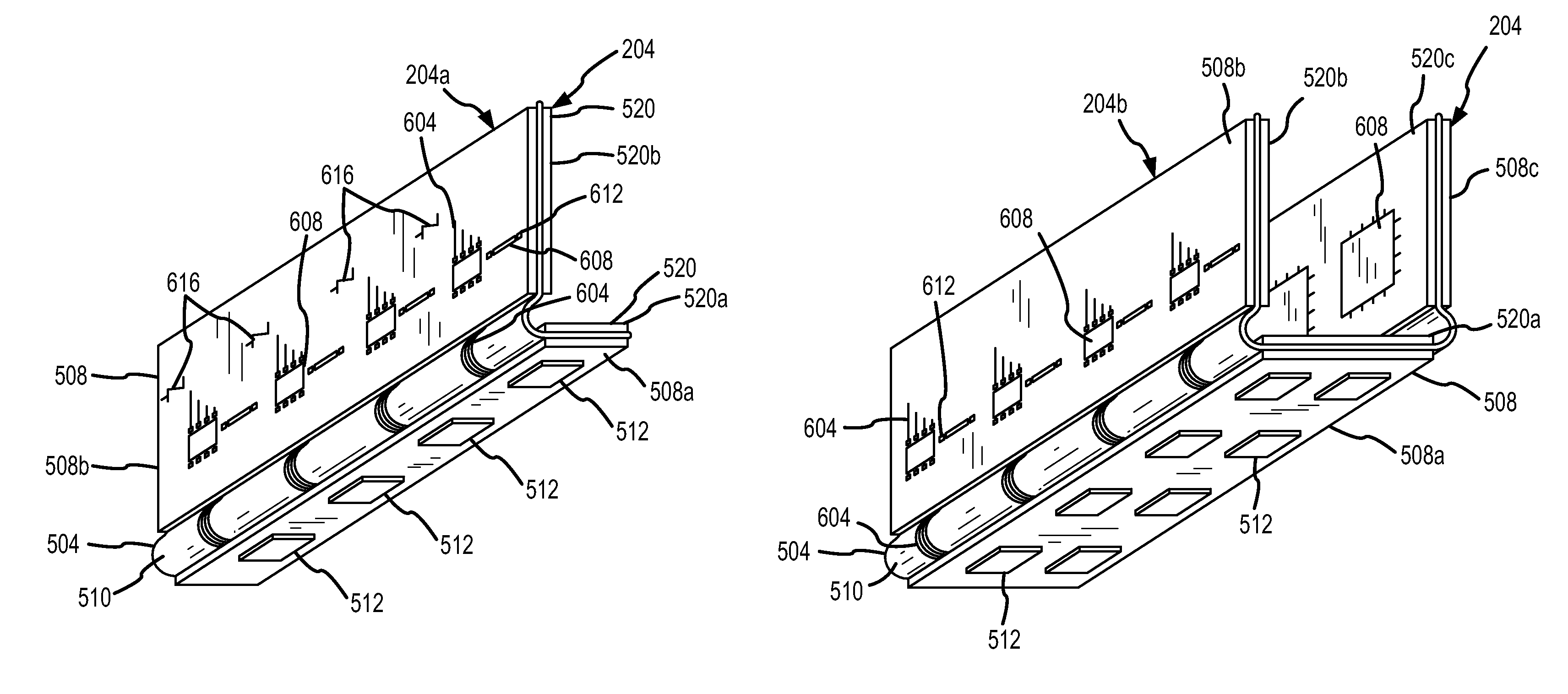
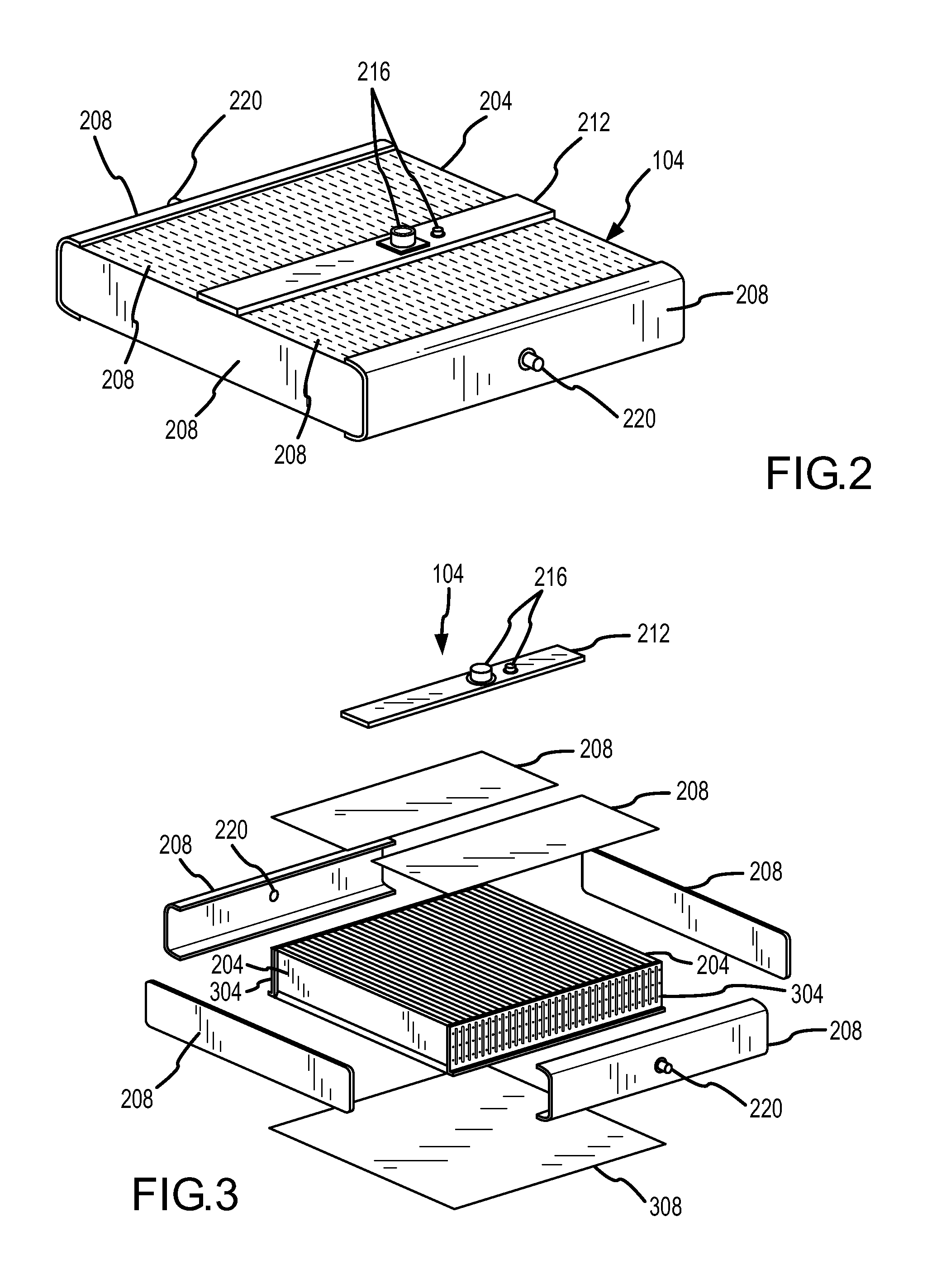
[0028]The present invention provides unit sub-arrays formed from interconnecting at least a first rigid circuit board to a flexible circuit board. More particularly, the unit sub-arrays feature antenna radiator elements that are interconnected to supporting circuitry in which the area available for creation and / or placement of the supporting circuitry is not limited to an area generally defined by the area of the radiator element or the area of the radiator elements plus at least one-half of the area between and / or surrounding the radiator elements. Furthermore, embodiments of the present invention facilitate the manufacture of phased array antennas by providing unit sub-arrays that can be manufactured as flat circuit boards using conventional techniques, including automated techniques. One application for such a modular architecture is the creation of phased array antenna assemblies.

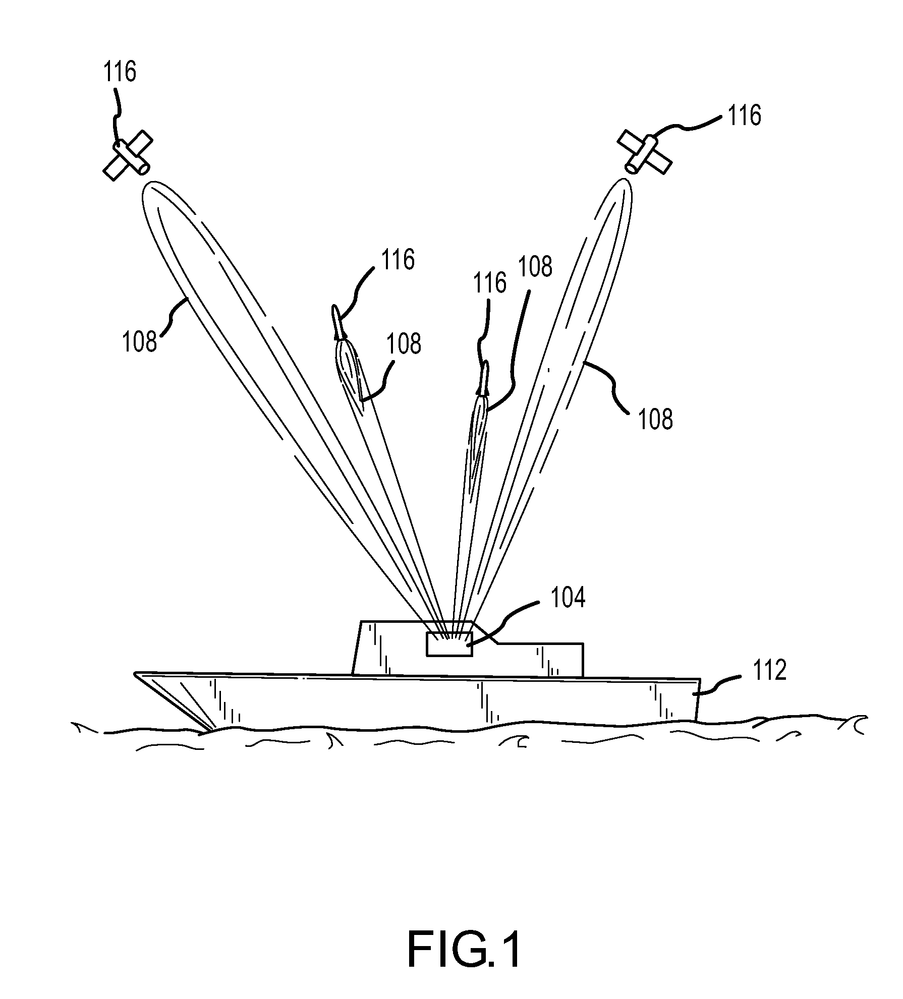
[0029]With reference now to FIG. 1, a phased array antenna assembly104 capable of forming and / or rec...


PUM


Abstract

A modular electronic architecture is provided. In particular, one or more unit sub-arrays providing at least a portion of the antenna radiator elements and supporting circuitry comprising at least part of a phased array antenna are provided. Each unit sub-array includes a first area comprising a rigid circuit board on which one or more antenna radiator elements are formed. In addition, a second area of rigid circuit board material for supporting circuitry is provided. The first and second areas are interconnected to one another by a region of flexible circuit board material having connective traces. Methods for forming unit sub-arrays providing antenna radiator elements and supporting circuitry are also provided. More particularly, a completed unit sub-array may be formed while the associated circuit boards are in a flat or planar condition. Following any desired verification of the operating status of the circuit board, supporting structure can be machined away, allowing the unit sub-array to be folded for inclusion in a phased array antenna assembly.

Description

FIELD OF THE INVENTION[0001]The present invention is directed to a modular electronic architecture. In particular, the present invention facilitates the efficient production and testing of antenna system circuit assemblies.BACKGROUND OF THE INVENTION[0002]Electronic circuits typically include a number of components. These components can be discrete devices, or provided as part of integrated circuits. Whether provided as discrete devices or integrated circuits, multiple electronic components are often interconnected to one another by placing those components on a common printed circuit board. In addition to providing a structural member to which components can be attached, a printed circuit board typically provides traces on one or more layers to conduct power and signals to and between attached components. When used in connection with implementing complex circuits, the design of the individual circuit boards can also become quite complex. In addition, where a large number of compone...

Claims


Application Information

Patent Timeline
IPC IPC(8): H01Q1/38H01Q21/00H01Q1/34
CPCH01Q21/0025H01Q21/065H05K3/4691
Inventor MOOSBRUGGER, PETER J.JENNINGS, RYAN S.TAME, BRADLEY J.
Owner BALL AEROSPACE & TECHNOLOGIES
Why Eureka
Try Eureka