Circuit for use with switched reluctance machines

a technology of switching resistance and switch, applied in the field of circuits, can solve the problems of device losses of 10% or more of the input power, device losses associated with the current in the switch and diode may be significant, and the loss of the total input power of the device will probably be below 3% of the total input power,

Active Publication Date: 2007-09-11
NIDEC SR DRIVES
View PDF27 Cites 13 Cited by
  • Summary
  • Abstract
  • Description
  • Claims
  • Application Information

AI Technical Summary

Benefits of technology

[0020]It is an object of embodiments of this invention to provide an efficient and economic...

Problems solved by technology

The losses associated with the currents in the switches and diodes may be significant, either with respect to the cooling of the devices themselves, to keep them within their thermal operating limits, or with respect to the overall efficiency of the drive.
In an industrial drive operating from, say, a 400V 3-phase supply and developing tens or hundreds of kilowatts, the device losses will probably be below 3% of the total input power.
In a low-voltage drive however, the devices losses can be 10% or more of the input.
One solution to this problem is to use devices with larger silicon area, and this will improve the situation to a limited extent, albeit at the expense of the size and cost of the devices.
However, in the generating mode the larger current often produces losses which are a serious drawback to efficient operation.
Firstly, the timing of the switching of the thyristor would ...

Method used


Image

  • Circuit for use with switched reluctance machines
  • Circuit for use with switched reluctance machines
  • Circuit for use with switched reluctance machines

Examples


Embodiment Construction

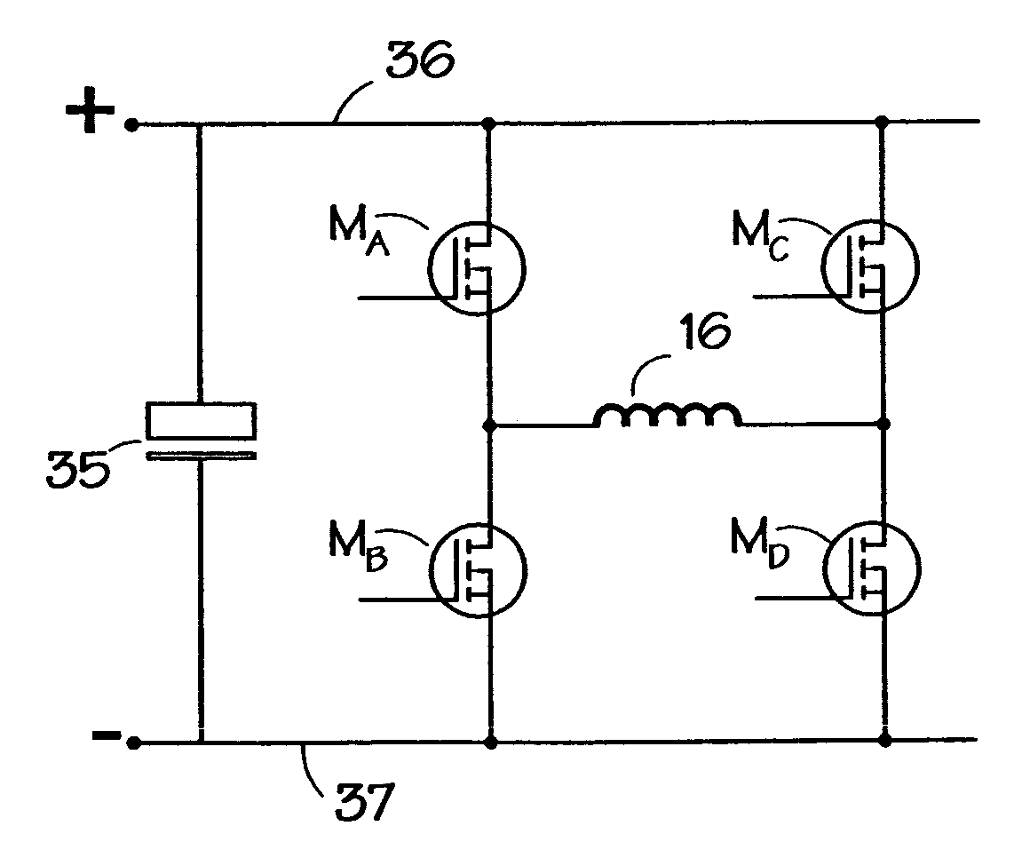
[0037]Embodiments of the invention take advantage of the characteristic of some switches which are able to conduct current in both directions and also to act as a diode at least on a transient basis. For example, a Metal-Oxide Silicon Field Effect Transistor (MOSFET) has desired characteristics. These characteristics are well-known in the art and are covered in standard texts, e.g. “Power Semiconductor Applications”, Philips Semiconductors, April 1991. Enhancement layer MOSFETs are one possible type of switch to be used.

[0038]As shown in FIG. 8, an embodiment of an excitation circuit for energizing a switched reluctance machine has four active switches MA, MB, MC, and MD, which are optionally MOSFETs, arranged in a bridge configuration around a phase winding 16. The switches are capable of conducting current in both a first direction and a second direction and are capable of operating as a diode. The direction of current flow through the phase winding 16 is reversed when changing fr...


PUM


Abstract

A switched reluctance machine is energized by phase circuits with four active switches, for example MOSFETs, arranged in a bridge configuration. The switches are capable of conducting current in both a first direction and a second direction and are capable of operating as a diode. The direction of current flow through the phase winding is reversed when changing from motoring to generating and from generating to motoring. The ratings of the switches are set in accordance with the energy supply and energy return currents.

Description

CROSS-REFERENCE TO RELATED APPLICATION[0001]The subject matter of this application is related to the subject matter of British Patent Application No. 0221154.8, filed Sep. 12, 2002, priority to which is claimed under 35 U.S.C. § 119 and which is incorporated herein by reference.BACKGROUND OF THE INVENTION[0002]1. Field of the Invention[0003]The present invention relates to a circuit for the efficient operation of switched reluctance machines, particularly those machines which are required to be operated in both motoring and generating modes.[0004]2. Description of Related Art[0005]In general, a reluctance machine is an electrical machine in which torque is produced by the tendency of its movable part to move into a position where the reluctance of a magnetic circuit is minimized, i.e. where the inductance of the exciting winding is maximized. In some forms, circuitry is provided for detecting the angular position of the rotor and energizing the phase windings as a function of the ro...

Claims


Application Information

Patent Timeline
IPC IPC(8): H02P23/00H02P25/08G11C29/00H02P6/00H02P6/14H02P27/06
CPCH02P25/085H02P9/40H02P25/092H02P25/08H02P27/06
Inventor TANKARD, MICHAEL PAUL
Owner NIDEC SR DRIVES
Why Eureka
Try Eureka