Method of NBTI prediction

a technology of negative bias and temperature instability, applied in the field of semiconductor device lifetime prediction of negative bias temperature instability (nbti) lifetime, can solve the problems of circuit failure to perform its function, degradation of transistor drive current for any given drive voltage, and degradation of reliability performance of the p

Inactive Publication Date: 2007-09-11
TAIWAN SEMICON MFG CO LTD
View PDF7 Cites 38 Cited by
  • Summary
  • Abstract
  • Description
  • Claims
  • Application Information

AI Technical Summary

Benefits of technology

[0014]In some embodiments, a method includes dividing a gate leakage current of at least one transistor by a corresponding gate voltage of the transistor to determine a ratio s. A single stress bias voltage is applied to the at least one transistor at a given temperature for a stress period t. The stress bias voltage is sufficiently high to cause a 10% degradation in a drive current of the transistor at the given temperature within the stress period t. A degradation slope n is determined, such that a change in the drive current of the transistor due to application of the single stress bias voltage is proportional to tn. A negative bias temperature instability (NBTI) lifetime τ of the transistor is estimated as a function of the ratio s of the gate leakage current to the gate voltage, and the degradation slope n determined from application of the single stress bias voltage.

Problems solved by technology

The mechanism is known to cause reliability performance degradation for the PFET because of this change in threshold voltage.
NBTI also results in degradation of transistor drive current for any given drive voltage.
A transistor that has decreased current output by 10% can have sufficient impact on circuit timing to cause the circuit to fail to perform its intended function, and is thus at the end of its useful life.
There has been controversy regarding these models and the selection of data points to be used in the models.
A model that underestimates the NBTI lifetime is troublesome, because it causes over-design of circuits and increases the cost of products that are required to last for a given specified product life.

Method used


Image

  • Method of NBTI prediction
  • Method of NBTI prediction
  • Method of NBTI prediction

Examples


Embodiment Construction

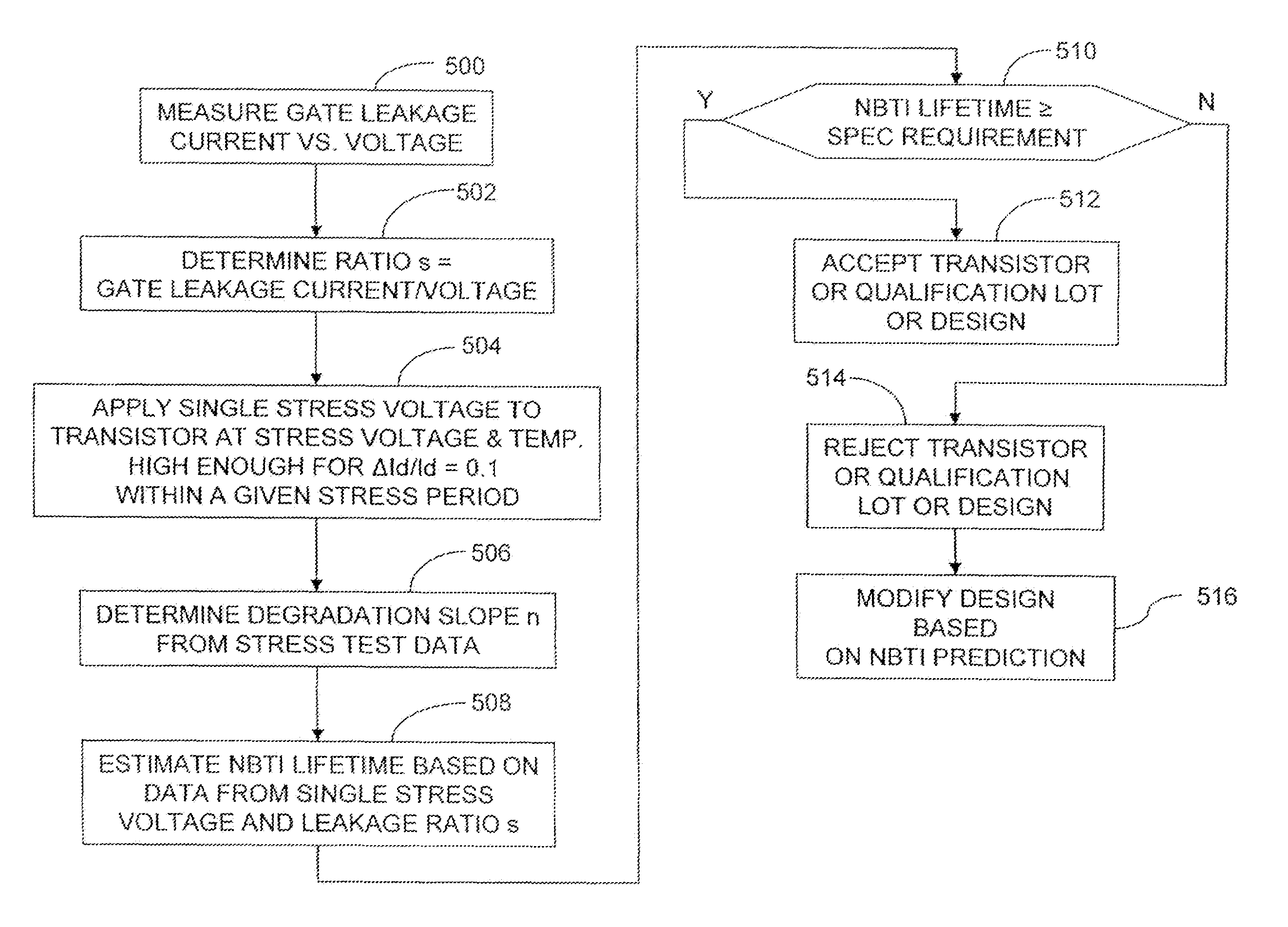
[0022]This description of the exemplary embodiments is intended to be read in connection with the accompanying drawings, which are to be considered part of the entire written description.

[0023]The literature has reported that NBTI degradation and gate leakage current mechanisms both are related to hole trapping, and that NBTI degradation in ultra thin oxide layers (as quantified by the fractional change in drive current) is proportional to the initial gate leakage current of the transistor. That is:

ΔId / Id˜Jg,  (2)

[0024]where ΔId / Id is the fractional change in drive current for a given drive voltage, and Jg is the gate leakage current.

[0025]The inventors of the present application have developed an NBTI prediction method based on equation (2). Gate leakage current can be plotted against gate voltage for a variety of gate oxide thicknesses, as shown in FIG. 3. When the natural logarithm of gate leakage current for a given transistor is plotted against the voltage Vg between the gate e...


PUM


Abstract

A method includes measuring a gate leakage current of at least one transistor. A single stress bias voltage is applied to the at least one transistor at a given temperature for a stress period t. The stress bias voltage causes a 10% degradation in a drive current of the transistor at the given temperature within the stress period t. A negative bias temperature instability (NBTI) lifetime τ of the transistor is estimated based on the measured gate leakage current and a relationship between drive current degradation and time observed during the applying step.

Description

FIELD OF THE INVENTION[0001]The present invention relates to semiconductor devices generally, and more specifically to prediction of Negative Bias Temperature Instability (NBTI) lifetimes in semiconductor devices.BACKGROUND[0002]Negative Bias Temperature Instability (NBTI) is a device degradation mechanism identified in sub-100 nm MOSFETs. When the gate of a P-MOSFET is negatively biased at an elevated temperature, oxide interface traps are generated due to an interaction of holes in the channel inversion layer with gate oxide. The instability is measured as an increase in the magnitude of the threshold voltage of the device. Higher stress temperatures produce more degradation. The mechanism is known to cause reliability performance degradation for the PFET because of this change in threshold voltage. NBTI also results in degradation of transistor drive current for any given drive voltage. NBTI becomes a serious concern for 90 nm technology and beyond, and its effect increases expon...

Claims


Application Information

Patent Timeline
Patent Type & Authority Patents(United States)
IPC IPC(8): G01R31/26
CPCG01R31/2642G01R31/3008G01R31/2858
Inventor CHEN, CHIA-LINCHEN, MING-CHEN
Owner TAIWAN SEMICON MFG CO LTD
Why Eureka
Try Eureka