Optical receiver decision threshold tuning apparatus and method

a technology of optical receiver and threshold tuning, which is applied in the direction of electrical equipment, transmission monitoring/testing/fault-measurement systems, transmission monitoring/testing/detecting systems, etc., can solve the problems of signal degradation, ber degradation, signal degradation, etc., and achieves high degree of utility for the invention, maintain ber performance, and rapid response

Active Publication Date: 2007-09-11
CIENA
View PDF22 Cites 44 Cited by
  • Summary
  • Abstract
  • Description
  • Claims
  • Application Information

AI Technical Summary

Problems solved by technology

It is well known that signals transported over optical communication networks suffer degradation between associated transmitters and receivers.
Signal degradation may result from a variety of system parameters including the total transmission distance, the transmission fiber type, the number of optical amplifications to a signal, the number of system channels, etc.
A difficulty with such receiver designs, however, is that the eye diagram itself depends on all of the above-mentioned parameters that effect signal quality.
Such changes can alter the received “eye diagram” leading to a degradation of the BER in the absence of a re-optimized decision threshold.
One problem is that channels passing through the same optical amplifier must share the same gain medium of the optical amplifier.
The illustration is most indicative of a fiber cut but there are a variety of circumstances that can lead to the failure of a subset of the channels being amplified by a common amplifier.
One can improve the time scale necessary to remove the extra energy available from the amplifier by designing faster amplifier control loops; however, it can't be completely eliminated.
However, some of the events described above can cause the channel 1 to drop within 20 to 50 microseconds.
Moreover, there is a snowball effect in optical networks due to the amplifier chain.
Nevertheless, such a traffic impact may very well occur as these kind of network events cause the receiver power as well as optical signal to change rapidly at the receiver.
In addition, optical signal traffic may need to be rerouted due to other concerns such as equipment maintenance, upgrades, and traffic load balancing.
The result of such protection switching and traffic rerouting is that the optical signal suddenly traverses a much longer (or perhaps shorter) distance and experiences a much greater (smaller) attenuation and distortion than before.
While such a protection switch recovery time is quite useful for the channel being rerouted, it does not help the other unswitched channels.
Such a fixed threshold is essentially a poor compromise for optimal performance and has significant impacts on the link budget thereby making it very difficult for high bit rate channels to be accommodated (nonlinear optical signal distortions typically increase with bit rate).

Method used


Image

  • Optical receiver decision threshold tuning apparatus and method
  • Optical receiver decision threshold tuning apparatus and method
  • Optical receiver decision threshold tuning apparatus and method

Examples


Embodiment Construction

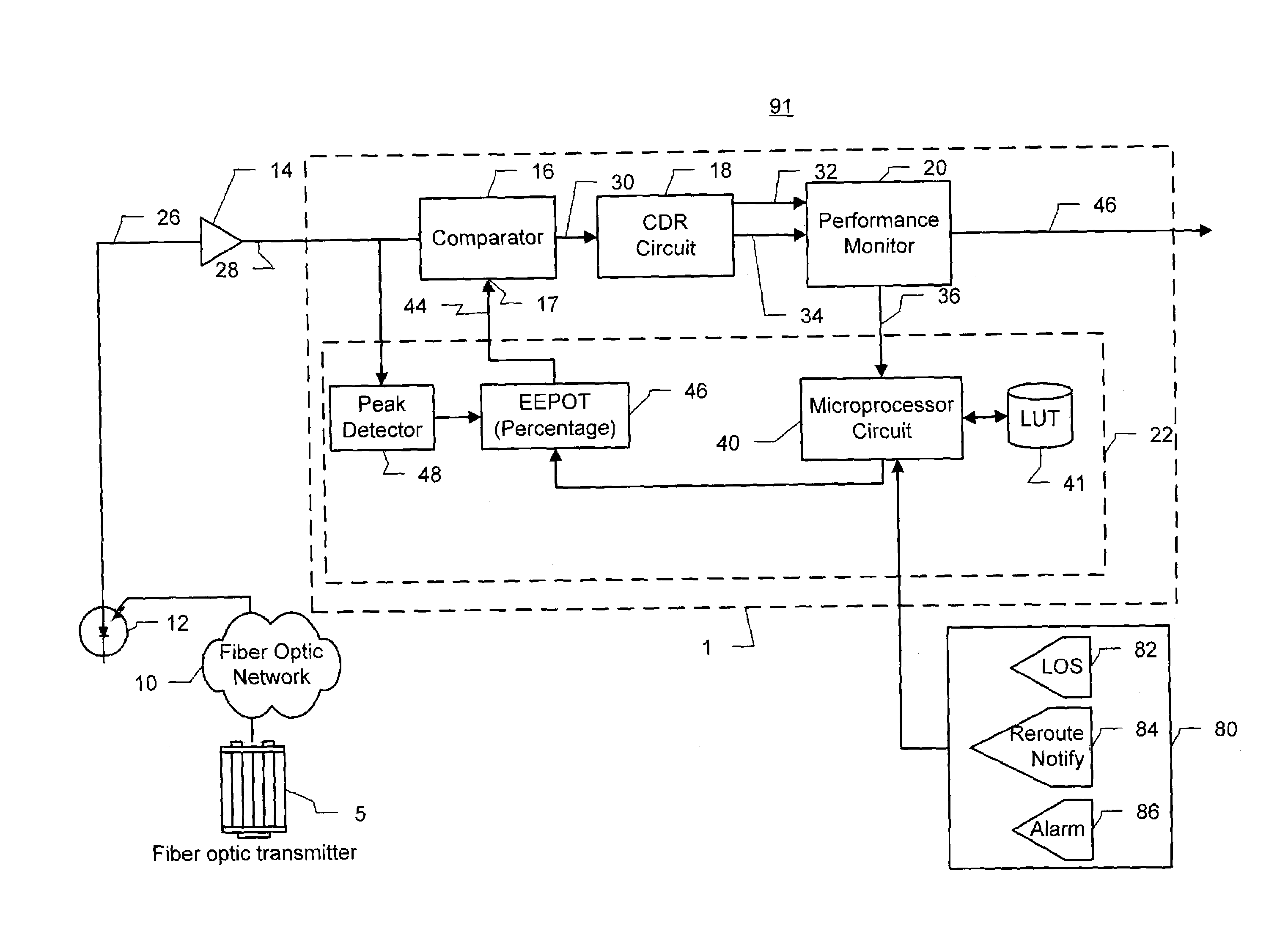
[0044]The following detailed description of the invention refers to the accompanying drawings. The same reference numbers in different drawings identify the same or similar elements. Also, the following detailed description does not limit the invention. Instead, the scope of the invention is defined by the appended claims and equivalents thereof.

[0045]The expression “optically communicates” as used herein refers to any connection, coupling, link or the like by which optical signals carried by one optical system element are imparted to the “communicating” element. Such “optically communicating” devices are not necessarily directly connected to one another and may be separated by intermediate optical components or devices. Likewise, the expressions “connection” and “operative connection” as used herein are relative terms and do not require a direct physical connection.

[0046]Furthermore, the terms “optimal”, “optimize” and the like do not necessarily refer to the absolute optimum. Inst...


PUM


Abstract

A method of controlling an optical signal receiver utilizes three control loops: a first control loop tunes the decision threshold of the receiver when the optical network is in a substantially steady state and a second control loop rapidly switches to a reference decision threshold upon the occurrence of an alarm condition. The invention rapidly switches to a predetermined reference decision threshold to compensate for optical signal changes in eye Q and received power after a protection switch or traffic reroute. After a protection switch, a slower tuning algorithm is used to adjust the decision threshold to a more optimum value. In the third control loop, the optical signal receiver may utilize a peak detector that detects the optical signal peak and a potentiometer that is commanded by a controller to output a commanded percentage of this peak value to adjust the threshold and thereby respond to transients.

Description

BACKGROUND OF THE INVENTION[0001]1. Field of Invention[0002]The present invention relates in general to receivers and methods of receiving for communication systems and, in particular, to an optical signal receiver and optical signal receiving method including decision threshold adjustment.[0003]2. Description of Related Art[0004]It is well known that signals transported over optical communication networks suffer degradation between associated transmitters and receivers. Signal degradation may result from a variety of system parameters including the total transmission distance, the transmission fiber type, the number of optical amplifications to a signal, the number of system channels, etc.[0005]Optical networks are, however, being developed with ever-increasing signal transmission speeds and distances. Channel counts have also been increasing in wavelength division multiplexed transmission systems. The greater transmission distances, speeds and higher channel counts directly effect...

Claims


Application Information

Patent Timeline
Patent Type & Authority Patents(United States)
IPC IPC(8): H04B10/08H04B17/00
CPCH04B10/66
Inventor MATRICARDI, ROCCODUNBAR, ANTHONYSHAH, SAURINBARNARD, CHRIS
Owner CIENA
Why Eureka
Try Eureka