Electrically motorized wheel with protective cover

a technology of motorized wheels and protective covers, which is applied in the direction of electric propulsion mounting, electric devices, transportation and packaging, etc., can solve the problems of loss of torque transmission, mechanical noise, and wear of parts, and achieve the effect of ensuring the effectiveness of torque transmission mechanisms and minimizing mechanical nois

Inactive Publication Date: 2007-09-18
DENSO CORP
View PDF20 Cites 21 Cited by
  • Summary
  • Abstract
  • Description
  • Claims
  • Application Information

AI Technical Summary

Benefits of technology

[0010]It is another object of the invention to provide a simple structure of an electrically motorized wheel assembly designed to protect a torque transmission mechanism installed within a wheel from foreign objects.
[0011]According to one aspect of the invention, there is provided an electrically motorized wheel assembly which may be employed in automotive vehicles, electrically-powered chairs, or electrically-powered carriers of robots. The motorized wheel assembly comprises: (a) an axle support designed to be joined to a body of a carrier to be equipped with the wheel assembly; (b) an axle supported rotatably by the axle support, the axle extending from the axle support in an axial direction thereof; (c) a wheel mounted on the axle to be allowed to revolve on the axle, the wheel being made up of a hollow cylindrical wall and a center wall extending from an inner peripheral surface of the cylindrical wall inward to form an inner chamber which has an opening oriented toward the body of the carrier; (d) a motor secured to the axle support to have an output shaft from which torque is outputted, the output shaft extending eccentrically from the axle and having a head extending into the inner chamber of the wheel close to the inner peripheral surface of the cylindrical wall of the wheel in substantially parallel to the axle; (e) a torque transmission mechanism working to increase the torque, as produced by the motor, and transmit it to the wheel, the torque transmission mechanism being disposed in the inner chamber of the wheel; and (f) a protective cover including a central hole through which the axle passes, an outer peripheral portion, and a motor mount. The outer peripheral portion extends inside the wheel through a gap between an outer circumference thereof and the inner peripheral surface of the cylindrical wall of the wheel. The motor mount has thereon the motor to have the head thereof extending inside the inner chamber of the wheel. The protective cover is retained by the axle support and extending in a radial direction of the wheel to substantially close the opening of the inner chamber of the wheel to hermetically enclose the torque transmission mechanism within the inner chamber, thereby protecting the torque transmission mechanism from foreign objects. This ensures the effectiveness of the torque transmission mechanism and minimizing mechanical noises therefrom.

Problems solved by technology

In the case of use in automotive vehicles, the motorized wheel is sometimes placed in severe environments such as dust or muddy water conditions, which leads to a greater concern about an increase in wear of the parts, loss of torque transmission, or mechanical noise.
The above problem usually underlies all types of motorized wheels, but however, the eccentric motor layout motorized wheel has the output shaft of the motor not located coaxially with the axle and, thus, encounters a difficulty in protecting the gear mechanism from dust without mechanical interference with the motor and the axle.
Of course, it is also difficult to employ a large-sized, complex sealing mechanism or a high-friction sealing mechanism.

Method used


Image

  • Electrically motorized wheel with protective cover
  • Electrically motorized wheel with protective cover
  • Electrically motorized wheel with protective cover

Examples


Embodiment Construction

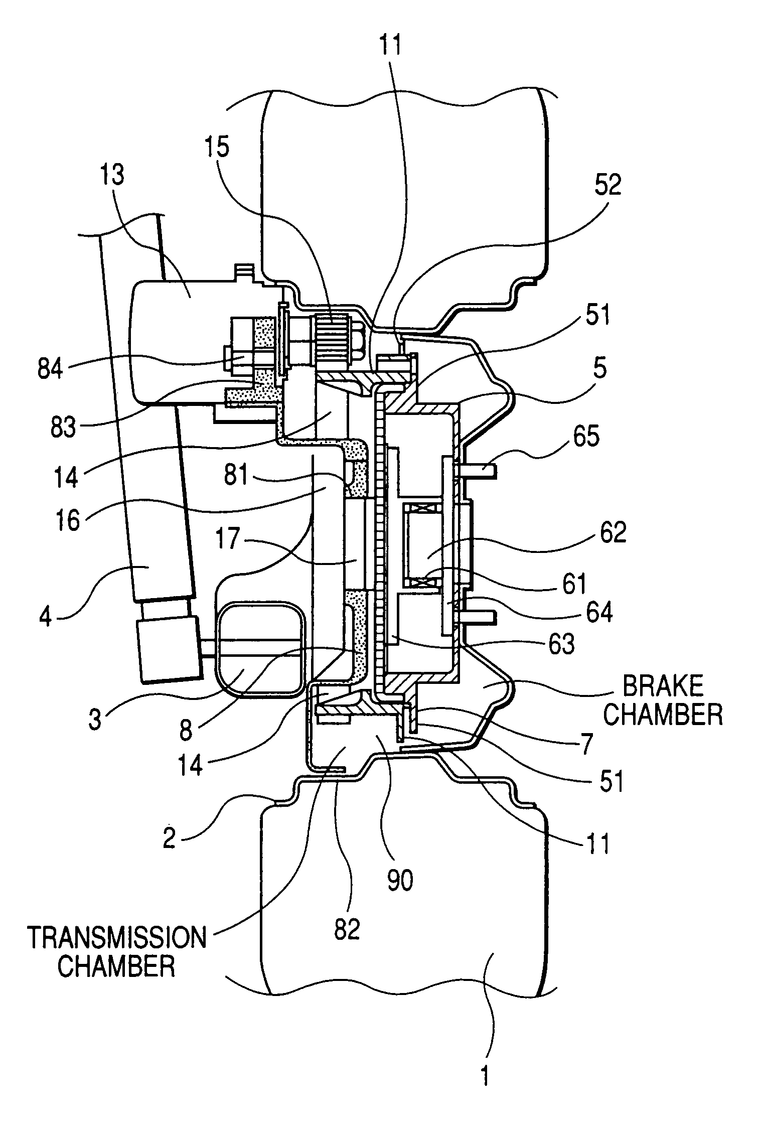
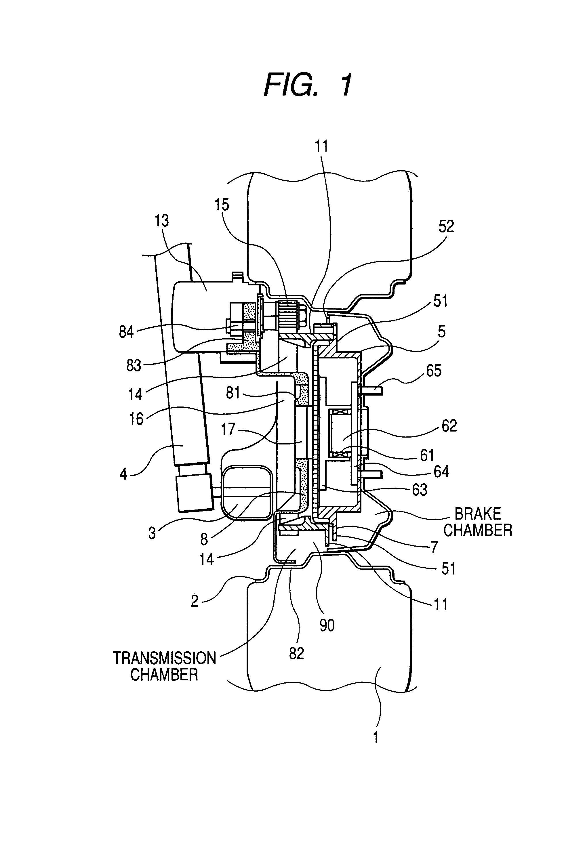
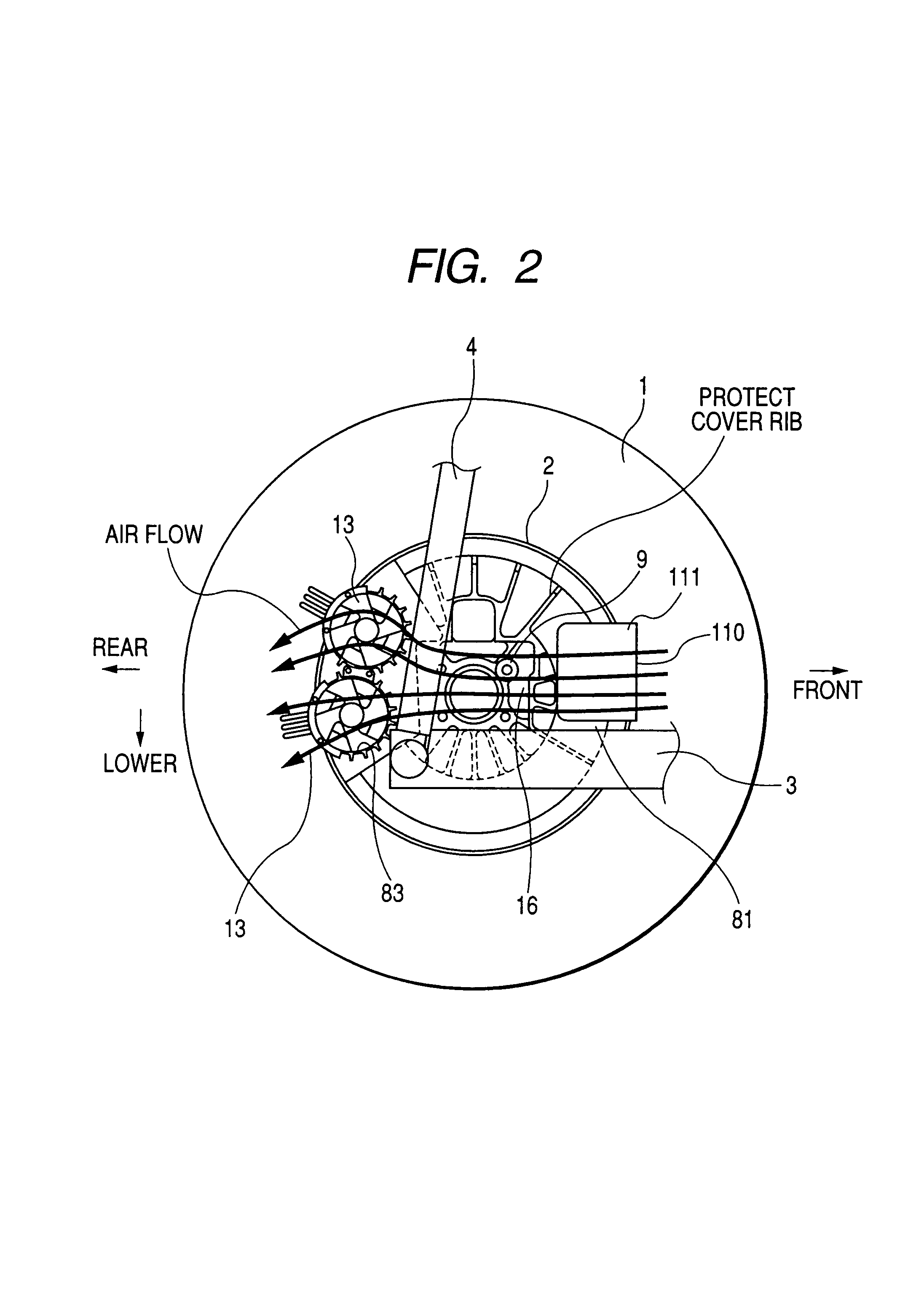
[0036]Referring to the drawings, wherein like reference numbers refer to like parts in several views, particularly to FIGS. 1 and 2, there is shown an electrically motorized wheel assembly according to the invention which will be discussed here as being used, as an example, in an automotive vehicle. The motorized wheel assembly may also be used in electrically-powered chairs or electrically-powered carriers for robots.

[0037]The motorized wheel assembly includes, like a standard automotive wheel, of a tire 1, a wheel 2, a trailing arm 3, a damper (shock absorber) 4, a brake drum 5, and axle bearing unit 6. The damper 4 is retained by a body of the vehicle and has a lower end by which the trailing arm 3 is retained. The trailing arm 3 is joined at an outside of front end thereof to the wheel 2 in which the brake drum 5 is built. The axle bearing unit 6 is installed within the brake drum 5. The tire 1 is mounted on the wheel 2. The tire 1, the wheel 2, the trailing arm 3, and the dampe...


PUM


Abstract

An electrically motorized wheel assembly is provided which may be used in automotive vehicles. The wheel assembly is equipped with at least one electric motor having an output shaft located eccentrically from an axle of a wheel. The wheel assembly includes a protective cover which closes an opening of the wheel to define a substantially enclosed inner chamber within which a belt-driven torque transmission mechanism is disposed to protect it from foreign objects.

Description

CROSS REFERENCE TO RELATED DOCUMENT[0001]The present application claims the benefit of Japanese Patent Application No. 2004-380028 filed on Dec. 28, 2004, the disclosure of which is incorporated herein by reference into this application.BACKGROUND OF THE INVENTION[0002]1. Technical Field of the Invention[0003]The present invention relates generally to an electrically motorized wheel assembly in which an electric motor is located eccentrically from an axle of a wheel for use in, for example, automotive vehicles, electrically-powered chairs, or electrically-powered carriers of robots, and more particularly to such an electrically motorized wheel assembly equipped with a protective cover.[0004]2. Background Art[0005]There are known electrically-powered carriers such as electric vehicles equipped with at least one pair of right and left motorized wheels each of which is driven by an electric motor. Motorized wheels of this type have the advantage that a differential gear or a long axle ...

Claims


Application Information

Patent Timeline
Patent Type & Authority Patents(United States)
IPC IPC(8): B60K1/00
CPCB60K7/0007B60K17/043B60K2007/003B60K2007/0061B60L2220/46
Inventor TANIGUCHI, MAKOTOMUKAI, TAKUZOU
Owner DENSO CORP
Why Eureka
Try Eureka