Electromagnetic suspension apparatus for automotive vehicles and method for controlling electric motor of the same

a technology of electric motors and suspension apparatus, which is applied in mechanical apparatus, shock absorbers, transportation and packaging, etc., can solve the problems of low follow-up performance of an unsprung mass, inability to adequately satisfy one-to-one correspondence between the output of the motor, and internal inertia, so as to reduce the driving stability containing both the vehicle drivability and the vehicle stability. , the effect of low follow-up performan

Inactive Publication Date: 2007-09-18
NISSAN MOTOR CO LTD
View PDF8 Cites 29 Cited by
  • Summary
  • Abstract
  • Description
  • Claims
  • Application Information

AI Technical Summary

Benefits of technology

[0003]In the electric-motor control method of the electromagnetically-operated suspension system of JP7-149130, an external inertia compensation for the inertia force exerted on the vehicle is taken into account. However, the motor control system of JP7-149130 does not consider an internal inertia compensation for an internal inertia force produced within the electromagnetic actuator, for example a moment of inertia of the motor rotor, and a moment of inertia of each of electromagnetic-actuator component parts displacing and rotating during the suspension stroke. Thus, the system of JP7-149130 cannot adequately satisfy one-to-one correspondence between the motor output and the electromagnetic actuator output. As a result of this, there is an increased tendency for the value of a frequency response of acceleration of a sprung mass for an input from a road surface to the suspension system to increase. This deteriorates a riding comfort. Additionally, in presence of a rapid displacement input from the road to the suspension system, the system of JP7-149130 may exhibit a low follow-up performance of an unsprung mass, thus lowering the driving stability containing both the vehicle drivability and vehicle stability. For the reasons discussed above, it would be desirable to compensate for the internal inertia force as well as the external inertia force.
[0004]Accordingly, it is an object of the invention to provide an electromagnetic suspension apparatus for an automotive vehicle and a method for controlling an electric motor incorporated in the electromagnetic suspension apparatus, capable of compensating for at least an internal inertia force, which is produced within an electromagnetic actuator of the electromagnetic suspension apparatus, thus greatly reconciling and balancing both of riding comfort and driving stability.
[0005]It is another object of the invention to provide an electromagnetic suspension apparatus for an automotive vehicle and a method for controlling an electric motor incorporated in the electromagnetic suspension apparatus, capable of compensating for an internal inertia force, which is produced within an electromagnetic actuator of the electromagnetic suspension apparatus, as well as an external inertia force, which is exerted on the vehicle, thus more greatly reconciling and balancing both of riding comfort and driving stability.

Problems solved by technology

However, the motor control system of JP7-149130 does not consider an internal inertia compensation for an internal inertia force produced within the electromagnetic actuator, for example a moment of inertia of the motor rotor, and a moment of inertia of each of electromagnetic-actuator component parts displacing and rotating during the suspension stroke.
Thus, the system of JP7-149130 cannot adequately satisfy one-to-one correspondence between the motor output and the electromagnetic actuator output.
Additionally, in presence of a rapid displacement input from the road to the suspension system, the system of JP7-149130 may exhibit a low follow-up performance of an unsprung mass, thus lowering the driving stability containing both the vehicle drivability and vehicle stability.

Method used


Image

  • Electromagnetic suspension apparatus for automotive vehicles and method for controlling electric motor of the same
  • Electromagnetic suspension apparatus for automotive vehicles and method for controlling electric motor of the same
  • Electromagnetic suspension apparatus for automotive vehicles and method for controlling electric motor of the same

Examples


Embodiment Construction

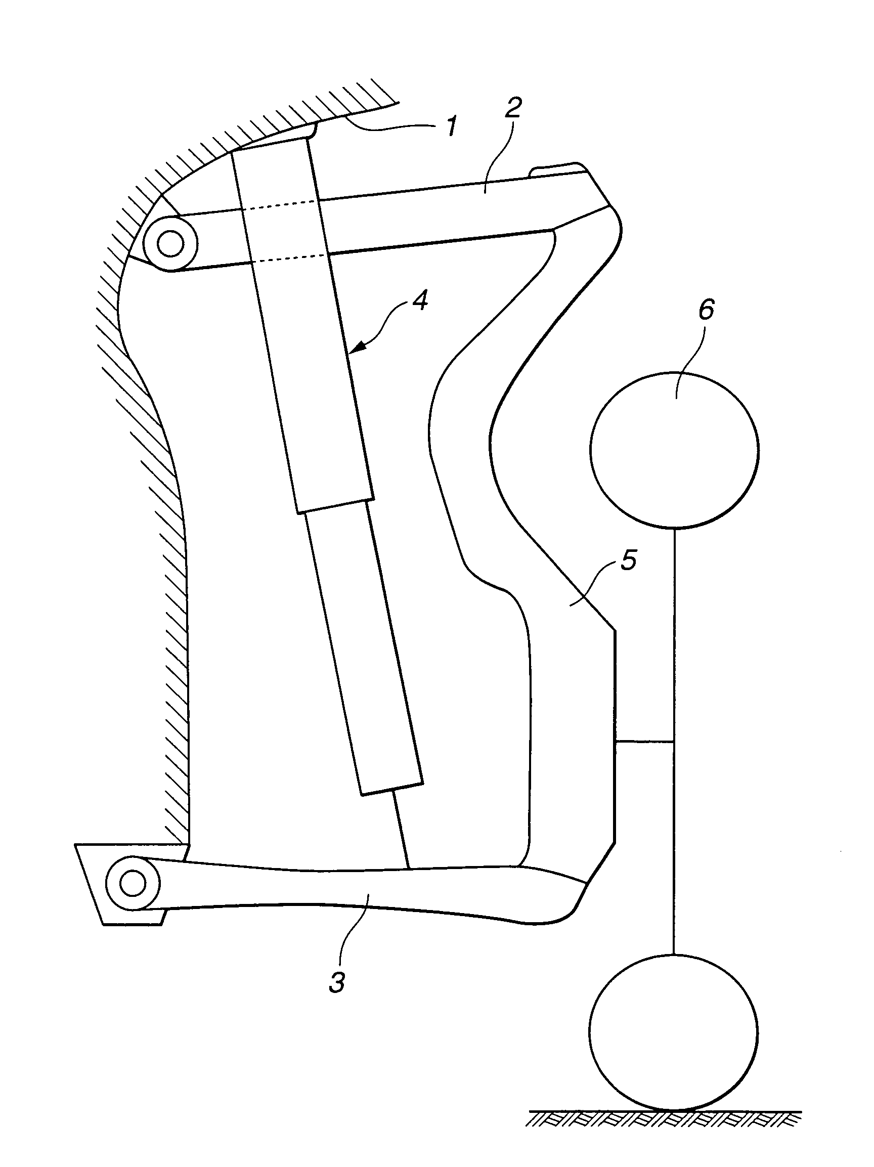
[0018]Referring now to the drawings, particularly to FIGS. 1 and 2, the automotive electromagnetic suspension apparatus of the embodiment is exemplified in an automotive vehicle employing multi-link independent suspensions at each road wheel.

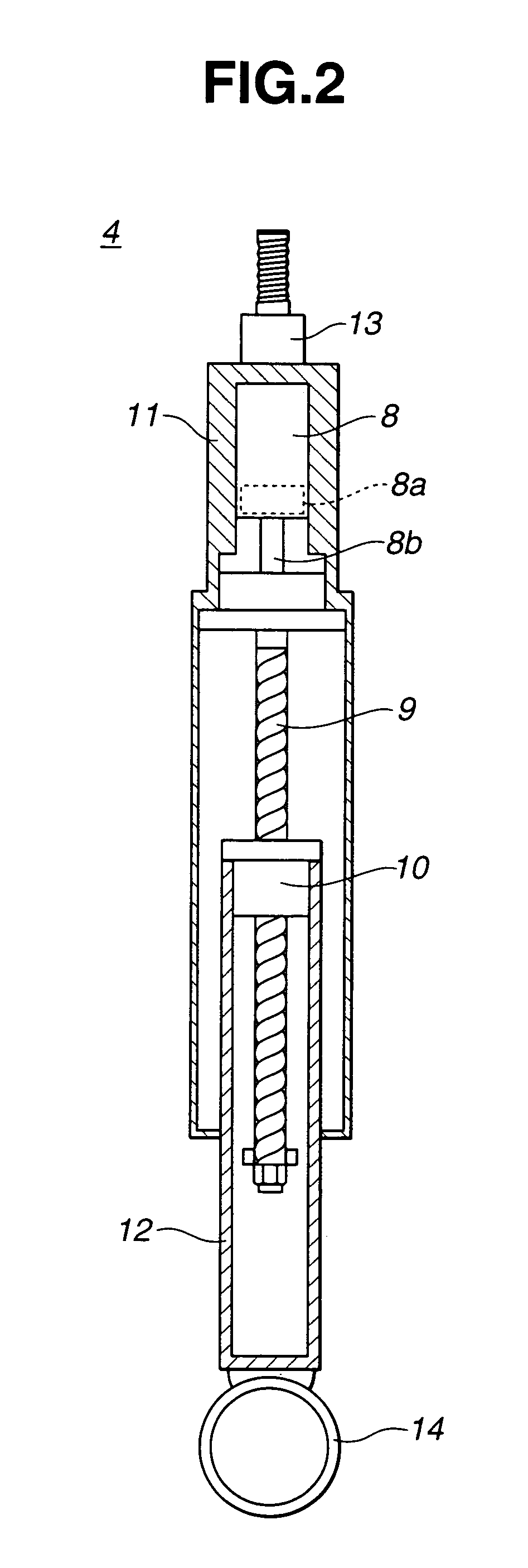
[0019]As shown in FIG. 1, the electromagnetic suspension apparatus of the embodiment, constructing the multi-link independent suspension system, is comprised of an upper link suspension-control-arm (simply, an upper link) 2, a lower link suspension-control-arm (simply, a lower link) 3, an electromagnetic actuator 4, an axle or a spindle 5, and a tire (an unsprung mass) 6. In the electromagnetic suspension system, electromagnetic actuator 4 is used instead of using a hydraulic damper or a hydraulic shock absorber. Electromagnetic actuator 4 is interleaved between a vehicle body 1 and lower link 3 and arranged in parallel with a suspension spring element (simply, a suspension spring) 7 having a suspension spring stiffness. To change the suspension...


PUM


Abstract

An electromagnetic suspension apparatus for an automotive vehicle, employs an electromagnetic actuator interleaved between a sprung mass and an unsprung mass and arranged in parallel with a suspension spring element, and an electric motor built in the electromagnetic actuator for driving the electromagnetic actuator. A motor controller calculates a displacement input, such as a suspension stroke acceleration and a suspension velocity, transmitted to the electromagnetic actuator, and controls the motor to bring a suspension damping force closer to a desired damping force suited for the displacement input. The motor controller calculates an internal inertia force of the electromagnetic actuator, and corrects or compensates for a motor output by the internal inertia force of the electromagnetic actuator.

Description

TECHNICAL FIELD[0001]The present invention relates to an electromagnetic suspension apparatus employing an electromagnetic actuator or an electromagnetic damper capable of electromagnetically dampening or attenuating vibrations input to the automotive suspension system, and particularly to the improvement of a motor-control technology for an electric motor incorporated in the electromagnetic suspension apparatus.BACKGROUND ART[0002]In recent years, automotive vehicles often use an electromagnetic suspension system instead of using a hydraulic damper of a hydraulically-operated active suspension system that uses a viscous resistance of oil. One such electromagnetic suspension system has been disclosed in Japanese Patent Provisional Publication No. 7-149130 (hereinafter is referred to as “JP7-149130”). In the electric motor type suspension system disclosed in JP7-149130, a motor of the electromagnetic suspension system acts to produce a reaction torque based on a motor rotation angle,...

Claims


Application Information

Patent Timeline
Patent Type & Authority Patents(United States)
IPC IPC(8): B60G17/015B60G13/14F16F15/03
CPCB60G17/0157F16F15/03
Inventor HIO, KOJIUNO, TAKAAKISATO, MASAHARU
Owner NISSAN MOTOR CO LTD
Why Eureka
Try Eureka