
Optical signal coupling

a technology of optical signal coupling and optical coupling, which is applied in the direction of anti-theft devices, rod connections, instruments, etc., can solve the problem of lowering the quality requirements of the optics of the signal coupling, and achieve the effect of wide useability, reliability and flexibility of the optical signal coupling, and further increasing the reliability and flexibility

Inactive Publication Date: 2007-09-18
ERA CONTACT
View PDF15 Cites 10 Cited by
  • Summary
  • Abstract
  • Description
  • Claims
  • Application Information

AI Technical Summary

Benefits of technology

[0011]Since the optical signals are intended to pass exclusively through the signal coupling they can be suited to the special optical characteristics of the signal coupling, so that the reliability of the signal transmission is substantially increased. If the signal coupling, for example as a result of contamination, abrasion, moisture or mechanical inaccuracies, produces a higher attenuation of the transmitted signals than expected, the signal created in the first coupling can be correspondingly strongly produced and the increased attenuation thereby compensated.
[0024]In a preferred further development the light opaque sleeves are electrically conducting and upon the pressing together of the end faces of the light conducting elements of the two coupling parts form an electrical contact between the associated sleeves through which electric signals are transmittable from one coupling part to the other coupling part. Thereby a second, independent channel for the transmission of signals is made which further increases the reliability of the optical signal coupling.

Problems solved by technology

Actually, because of this compensation possibility a certain optical attenuation by the signal coupling is acceptable, which lowers the quality requirements for the optics of the signal coupling.

Method used


Image

  • Optical signal coupling
  • Optical signal coupling
  • Optical signal coupling

Examples


Embodiment Construction

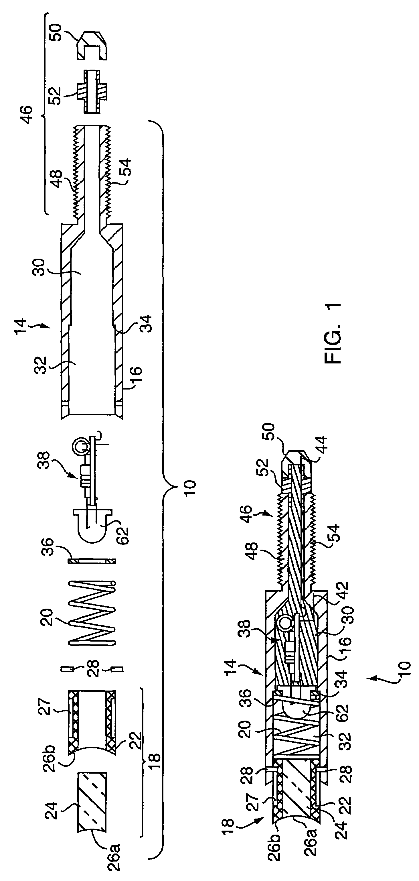
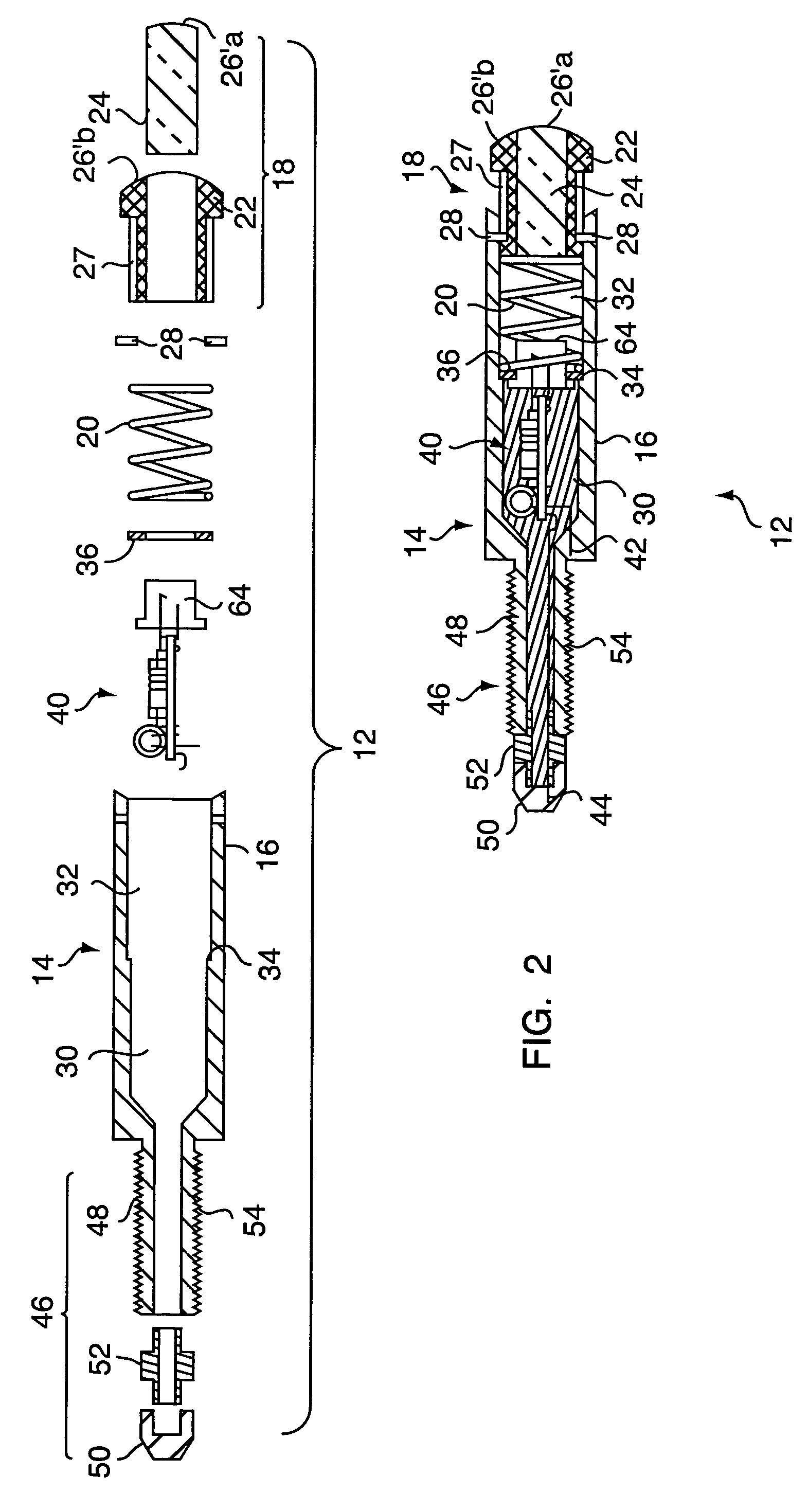
[0044]Shown in FIG. 1 is a longitudinal sectional view of the first coupling part 10 of a signal coupling according to a development of the present invention in exploded illustration (upper) and in assembled condition (lower). In FIG. 2 is shown a longitudinal sectional illustration of the second coupling part 12 of the same signal coupling in exploded illustration (upper) and in assembled condition (lower). Since the first and the second coupling parts 10 and 12 are identical in many features, they will be described in common in the following with similar parts being indicated by the same reference characters.

[0045]The coupling parts 10 and 12 each have a housing 14 with a sleeve-like section 16 in which a light conducting element 18 is axially slidably supported. The light conducting element 18 can be pressed into the sleeve-like section 16 of the associated housing 14 against the biasing force of a spring 20. In place of the spring 20, the light conducting element 18 can also be...


PUM


Abstract

Described are an optical signal coupling for two vehicles coupled with one another and a conductive coupling which contains such a signal coupling. The signal coupling has a first and a second coupling part each of which is carried by a respective one of the vehicles and between which the optical signals are transmitted. The first coupling part contains a sending device which creates the optical signals to be transmitted, and the second coupling part contains a receiving device which detects the transmitted optical signals.

Description

CROSS-REFERENCE TO RELATED APPLICATIONS[0001]This application is entitled to the benefit of and incorporates by reference essential subject matter disclosed in German Patent Application No. 103 10 134.9 filed on Mar. 7, 2003.FIELD OF THE INVENTION[0002]The present invention concerns an optical signal coupling for two vehicles coupled with one another, especially rail vehicles coupled with one another, with a first coupling part carried by one of the vehicles and a second coupling part carried by the other of the vehicles, between which parts optical signals are transmitted. The invention further concerns a conductive coupling for rail vehicles, which coupling contains at least one of such signal couplings.BACKGROUND OF THE INVENTION[0003]In vehicle technology for signal and data transmission, light conductors are becoming used in increasing numbers which, in contrast to a customary electrical signal conductors, provide substantial advantages. Among these advantages are their larger ...

Claims


Application Information

Patent Timeline
Patent Type & Authority Patents(United States)
IPC IPC(8): G02B6/38B60R11/00G02B6/42G02B6/24B61G5/10F16B7/20F16C11/06F16C11/08H01L31/0232H01L33/00H01L33/48
CPCB61G5/10G02B6/3821
Inventor MEYER, MARTIN WOLFGANG
Owner ERA CONTACT
Learn More