Phosphor having resistance to deterioration caused by ultraviolet rays, and gas discharge display device of which image quality is not readily deteriorated over time

a technology of ultraviolet rays and phosphor, which is applied in the direction of discharge tube luminescent screens, discharge tube/lamp details, luminescent compositions, etc., can solve the problems of deteriorati insufficient reduction of deterioration over time, and deterioration of luminous efficiency, so as to reduce the deterioration of phosphor over time and not readily deteriorate over time.

Inactive Publication Date: 2007-09-18
PANASONIC CORP
View PDF4 Cites 6 Cited by
  • Summary
  • Abstract
  • Description
  • Claims
  • Application Information

AI Technical Summary

Benefits of technology

[0017]The first object of the present invention is to solve the above-described problems, and therefore to provide a manganese-activated zinc silicate phosphor in which the luminance of the emitted light is maintained at the conventional level and the deterioration of the phosphor over time is reduced. The second object of the present invention is to provide a gas discharge display device in which the luminance is maintained at the conventional level and the phosphor is not readily deteriorated over time.

Problems solved by technology

By the way, the manganese-activated zinc silicate phosphor has a problem to be solved, that is, the luminous efficiency might be deteriorated over time, depending on the way it is used.
However, it can not sufficiently reduce the deterioration over time in the case where ultraviolet rays having a short wavelength and high energy is used as the excitation light, like in the case of the PDPs.
The method disclosed by the Document 2 has another problem as well, that is, if a compound layer other than the manganese-activated zinc silicate phosphor is formed on the surface of the phosphor particle, the ultra violate ray, which is the excitation light, and the visible light generated by the light emission might be absorbed by the compound layer, and this greatly deteriorates the luminous efficiency.
Meanwhile, the inventors manufactured several trial models of the phosphor according to the Document 3 for each of which the composition ratio in the whole phosphor particle is modified, and the inventors found that it is difficult to reduce the deterioration over time and the phosphor of the Document 3 is not practical.
In other words, the inventors found that simply adjusting the elemental composition ratio in the whole particle is not enough to control and stabilize the elemental composition ratio in the particulate surface region of the particle, which contributes to the light emission.

Method used


Image

  • Phosphor having resistance to deterioration caused by ultraviolet rays, and gas discharge display device of which image quality is not readily deteriorated over time
  • Phosphor having resistance to deterioration caused by ultraviolet rays, and gas discharge display device of which image quality is not readily deteriorated over time
  • Phosphor having resistance to deterioration caused by ultraviolet rays, and gas discharge display device of which image quality is not readily deteriorated over time

Examples


Embodiment Construction

Structure

1. Structure

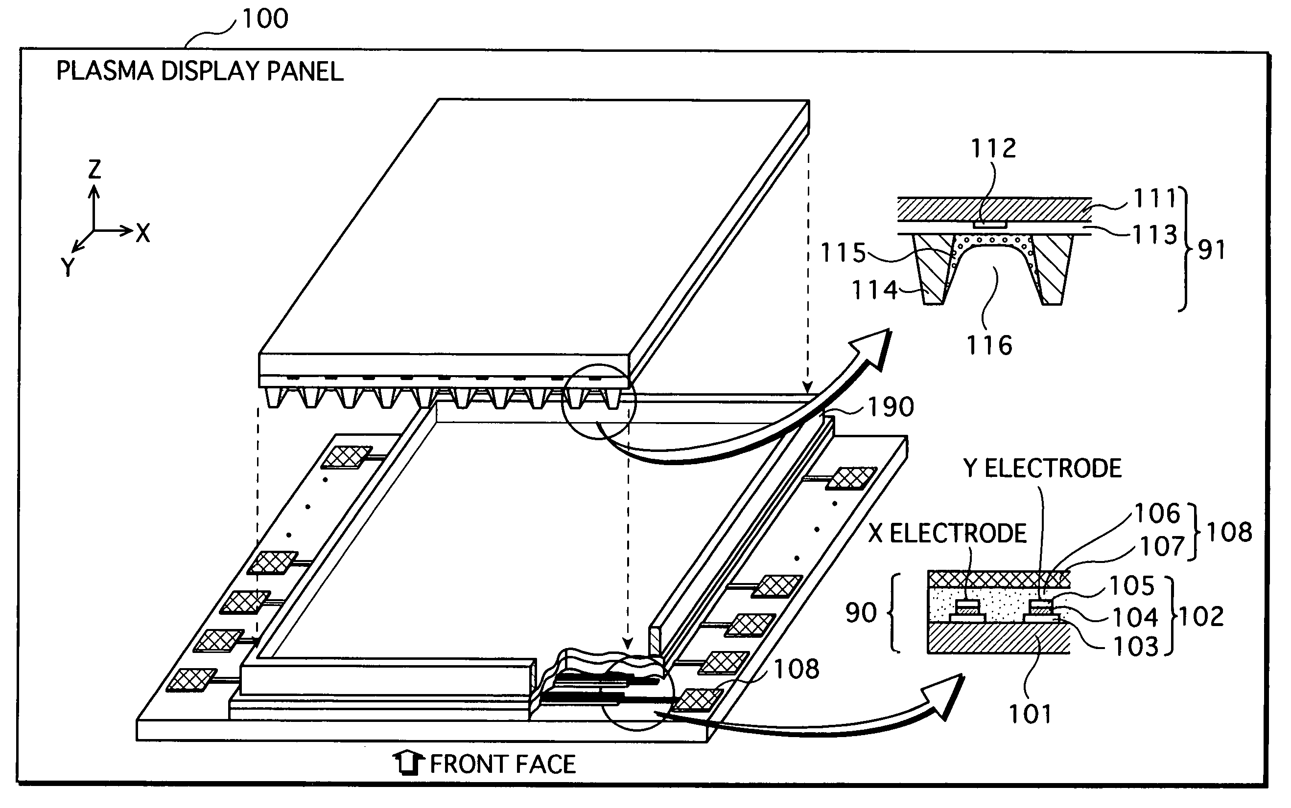
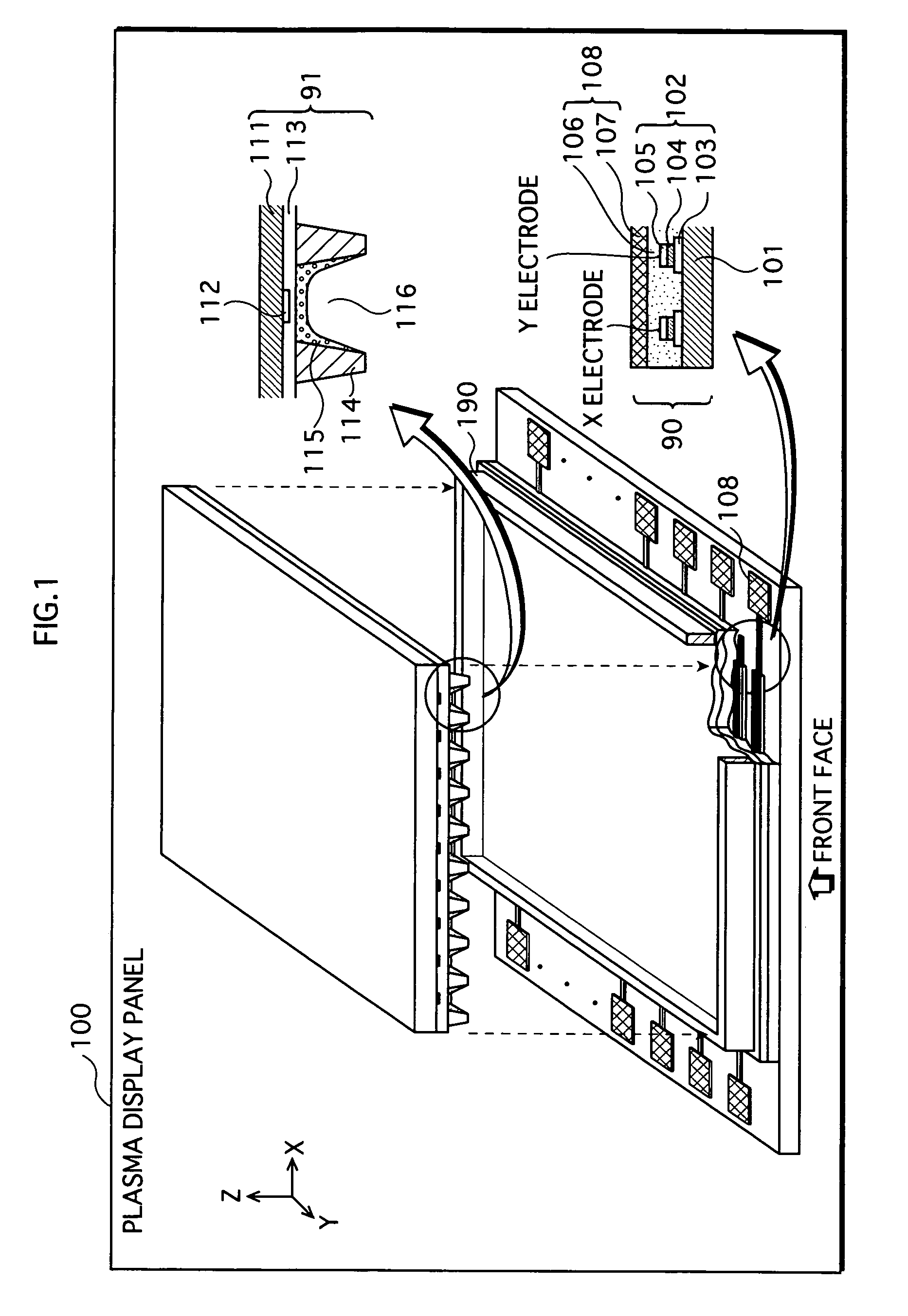
[0041]FIG. 1 is a schematic view of a PDP as an example of a gas discharge display device according to an embodiment of the present invention.

[0042]A PDP 100 is an alternate-current type (AC type) PDP. The PDP 100 includes a front plate 90 and a back plate 91. The main surfaces of those plates oppose each other.

[0043]The front plate 90 includes a front glass substrate 101, a display electrode 102, a dielectric layer 106, and a protective layer 107.

[0044]The front glass substrate 101 is a base for the front plate 90, and the display electrode 102 is formed on the front glass substrate 101.

[0045]The display electrode 102 includes a transparent electrode 103, a black electrode film 104, and a bus electrode 105.

[0046]The main component of the black electrode film 104 is ruthenium oxide, which takes on a black color. This prevents the reflection of outside light when viewed from the back side of the glass.

[0047]The bus electrode 105 is mainly composed of silver that ...


PUM

PropertyMeasurementUnit
depthaaaaaaaaaa
pressureaaaaaaaaaa
pressureaaaaaaaaaa

Abstract

A manganese-activated zinc silicate phosphor according to the present invention satisfies 0<β−α≦0.5 and 1.7≦β, where a value α is a ratio of a number of zinc atoms to a number of silicon atoms in a surface region of a phosphor particle, including a surface of the phosphor particle and a vicinity thereof, and a value β is a ratio of a number of zinc atoms to a number of silicon atoms in a whole of the phosphor particle.

Description

BACKGROUND OF THE INVENTION[0001](1) Field of the Invention[0002]The present invention relates to a manganese-activated zinc silicate phosphor, and particularly relates to techniques for preventing the phosphor from being deteriorated by ultraviolet rays, and preventing the image quality of a gas discharge display device that uses the phosphor from being deteriorated over time.[0003](2) Description of the Related Art[0004]A manganese-activated zinc silicate phosphor is commonly used as a green light emitting material for fluorescent lamps and plasma display panels (herein after called “PDPs”). The green light emitting material uses ultraviolet rays as an excitation light source. The manganese-activated zinc silicate phosphor is particularly often used for gas discharge display devices, such as the PDPs, because of its high color purity and high luminous efficiency.[0005]The parent body of the manganese-activated zinc silicate phosphor, which is zinc silicate, is expressed by a gener...

Claims


Application Information

Patent Timeline
Patent Type & Authority Patents(United States)
IPC IPC(8): C09K11/59C09K11/54C09K11/57C09K11/77H01J11/12H01J11/42
CPCC09K11/595C09K11/7734C09K11/7797H01J11/42H01J11/12C09K11/57
Inventor NAGASAKI, YOSHIHISASHIRAISHI, SEIGOSAKAI, MASAHIRO
Owner PANASONIC CORP
Why Eureka
Try Eureka