Method and system for providing performance estimations for a specified power budget

Inactive Publication Date: 2007-09-18
IBM CORP
View PDF3 Cites 63 Cited by
  • Summary
  • Abstract
  • Description
  • Claims
  • Application Information

AI Technical Summary

Benefits of technology

[0015]The power measurements at each interval may be collected in a histogram, incrementing a bin corresponding to the data value or range in which the power value falls at the end of each interval. The histogram counts can then be totaled and the counts for bins exceeding the budgetary level along with the amount by which the bin exceeds the budgetary level used to determine the effect on performance.
[0016]Alternatively, the power level may be observed as a continuous timeline and for each interval in which the power budget exceeded the budgetary limit, a factor by which that interval exceeded the power budget used to estimate the effect on the length of the interval (i.e., how long would that portion of the workload taken to complete at a performance level that meets the power bud

Problems solved by technology

Further, under power supply fault conditions, it is possible to continue operating at a lower power level when multiple power supplies are available and one of them has failed.
However, automatic control of the system performance by the dynamic power management solutions mentioned above makes it difficult to predict how power management will affect performance for a given workload, as the power control system will dynamically change the performance of the system in order to maintain a specified power budget.
For example, a power budget may hardly affect system power/performance at one level, but another nearly identical power/performance level may have a more severe impact on the system.
Since the behavior is non

Method used


Image

  • Method and system for providing performance estimations for a specified power budget
  • Method and system for providing performance estimations for a specified power budget
  • Method and system for providing performance estimations for a specified power budget

Examples


Embodiment Construction

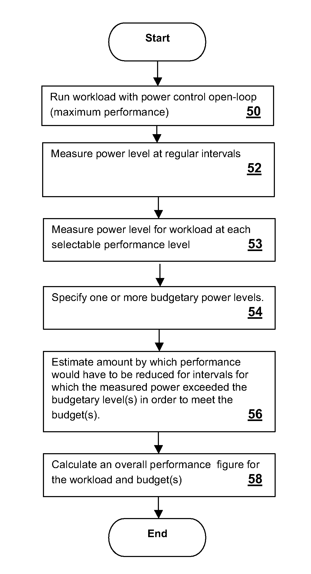
[0025]The present invention concerns a technique for performance estimation in a processing system that employs power / performance control to meet budgetary requirements. For a set of tabulated power budgets, or a user-specified power budget, the method estimates the performance of the processing system for a given workload. The workload may be a predetermined reference workload, a user-selected workload from set of reference workloads, or an actual workload set up by a user, generally a system administrator or integrator.

[0026]The techniques of the present invention provide a performance figure of merit for a given workload under controlled execution at a given power budget without requiring that the workload be actually run at the power budget at controlled execution. Rather, the workload or similar reference workload is run with the power / performance control system disabled or “open-loop” so that the workload is executed at the maximum performance level. The power consumption is t...


PUM


Abstract

A method and system for providing performance estimations for a specified power budget provides an indication of the impact on processing performance when closed-loop power/performance control is employed to meet the specified power budget. A workload, which may be the actual workload, or a test workload is run to determine actual power consumption at intervals during the execution of the workload. The power values are examined and if they exceed the specified budget, which may be one of multiple possible budget values, an estimate of the amount by and duration for which the closed-loop power/performance control would have to reduce the performance of the system for each interval in order to provide an estimate of actual performance for the budgetary level(s). The estimate is informed by tests of the workload at each power/performance level to provide a non-linear estimate of the relationship between performance and power for the particular workload.

Description

CROSS-REFERENCE TO RELATED APPLICATIONS[0001]The present application is related to previously-filed co-pending U.S. patent application Ser. No. 11 / 289,249 filed on Nov. 29, 2005 and entitled “HISTOGRAM DIFFERENCE METHOD AND SYSTEM FOR POWER / PERFORMANCE MEASUREMENT AND MANAGEMENT.” The above-referenced Patent Application has at least one inventor in common with the present application and is assigned to the same assignee. The specification of the above-referenced Patent Application is incorporated herein by reference.BACKGROUND OF THE INVENTION[0002]1. Technical Field[0003]The present invention relates generally to power / performance measurement and management in processing systems, and more particularly, to an estimation scheme that can predict a measure of computing performance from a specified power budget.[0004]2. Description of the Related Art[0005]Vendors of multiple processor servers and other medium to large-scale data processing systems are finding it increasingly necessary t...

Claims


Application Information

Patent Timeline
IPC IPC(8): G01R21/00G06F15/00
CPCG06F11/3409G06F11/3452G01R21/1333G06F2201/88Y02B60/165Y02D10/00
Inventor BREY, THOMAS M.FELTER, WESLEY M.LEFURGY, CHARLES R.RAJAMANI, KARTHICKRUBIO, JUAN C.WARE, MALCOLM S.
Owner IBM CORP
Why Eureka
Try Eureka