Dark fiber laser array coupler

a technology of optical oscillator array and dark fiber laser, which is applied in the field of lasers, can solve the problems of increasing the complexity of the system disclosed by brosnan, the cost and difficulty of the apparatus described by abrams et al., and the relatively low power output of a single fiber laser without amplification or other power increasing techniques, so as to increase the losses of the composite laser array

Inactive Publication Date: 2007-09-25
HRL LAB +2
View PDF35 Cites 20 Cited by
  • Summary
  • Abstract
  • Description
  • Claims
  • Application Information

AI Technical Summary

Problems solved by technology

Hence, the apparatus described by Abrams et al. may be expensive and difficult to implement.
However, the power output of a single fiber laser without amplification or other power increasing techniques is relatively low.
However, the additional circuitry required to detect and compensate for the relative optical phase shifts increases the complexity of the system disclosed by Brosnan.
Also, fiber amplifiers are generally less efficient than fiber oscillators (lasers).
Hence, the system disclosed by Brosnan would be considered more complex and less efficient than a system based on a plurality of fiber oscillators.
However, this configuration does not provide for phase-locking between the light propagating in each of the cores.
A key problem with multiple-core fiber oscillator systems, such as the system disclosed by Scifres, is heat dissipation.
Hence, the power of the multiple-core fiber oscillator systems will be limited by the ability to dissipate the heat generated by the active regions away from the multiple-core fiber, similar to the way that glass rod lasers are limited in average power scaling.
Furthermore, as the optical power in each fiber is increased, this prior art has the disadvantage that the combined power must propagate in the core of the single central fiber.
When the combined optical power is high, undesirable nonlinear effects in, or damage to, the single central fiber may occur.
Further, the acoustic waves may also be amplified by this effect, generating an acoustic intensity that can easily damage the single central fiber.
Splitting a single optical source into multiple optical outputs may also be provided by the 1×N star coupler described above, but the power handling capabilities of the coupler are again limited by the single central fiber.
Even assuming perfect alignment, the coupling efficiency is limited by the packing of both the fibers in the fiber bundle and the lenses in the array of lenses.
The coupling efficiency is further limited by clipping that occurs at the edge of each lens in the array.
Therefore, even though the optical plane wave may be a high power optical beam, a significant portion of that power is lost when coupling the beam into multiple fibers using apparatus and methods known in the art.
Such approaches complicate the design and / or fabrication of systems in which multiple laser sources are used to generate high power outputs.
However, if the light reflected from the cleaved coupler face deviates from the ideal, then light propagates in the broken or lossy fibers, and there is a net loss of light.

Method used


Image

  • Dark fiber laser array coupler
  • Dark fiber laser array coupler
  • Dark fiber laser array coupler

Examples


Embodiment Construction

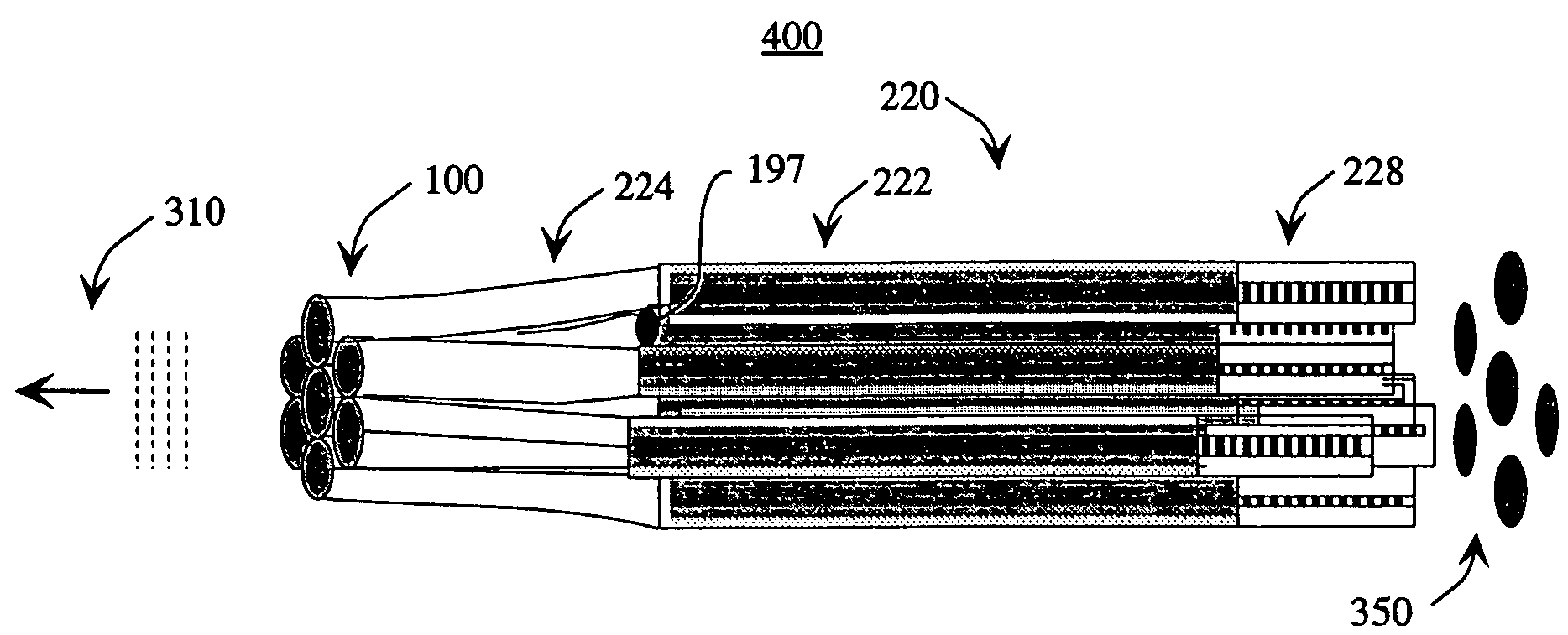
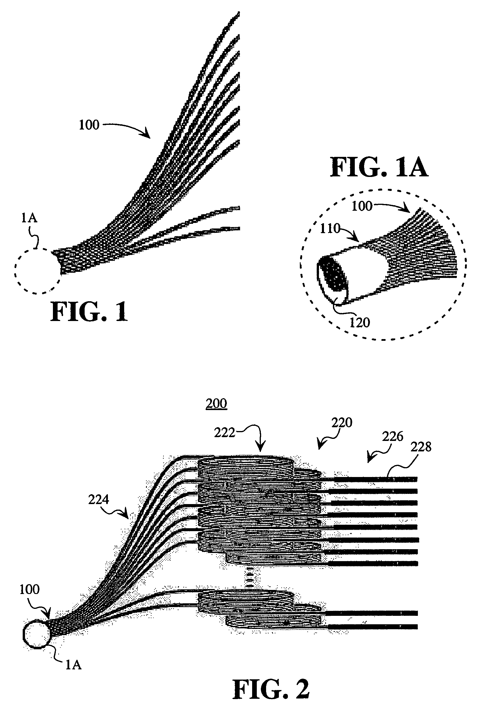
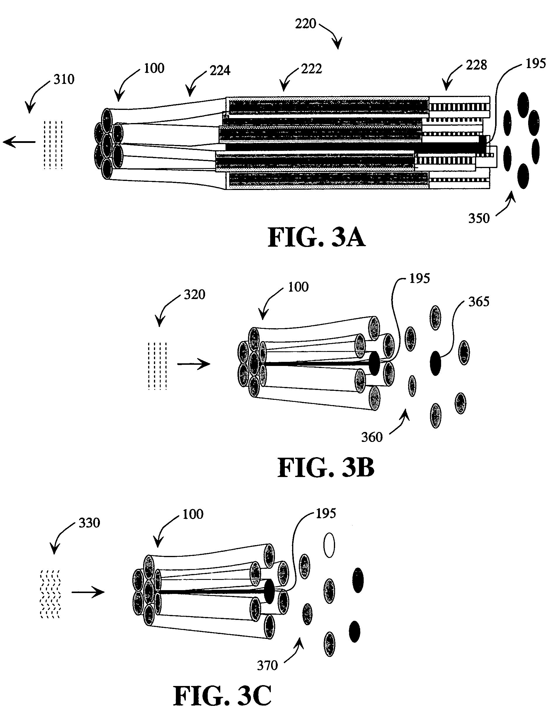
[0041]The present invention will now be described more fully hereinafter with reference to the accompanying drawings, in which preferred embodiments of the invention are shown. This invention may be embodied in many different forms and should not be construed as limited to the embodiments set forth herein. Further, the dimensions of certain elements shown in the accompanying drawings may be exaggerated to more clearly show details. The present invention should not be construed as being limited to the dimensional relations shown in the drawings, nor should the individual elements shown in the drawings be construed to be limited to the dimensions shown.

[0042]FIG. 1 illustrates an optical coupler for use in embodiments of the present invention, in which the optical coupler 100 comprises a large bundle of regularly arrayed optical fibers 110. The optical fibers 110 are preferably single-mode fibers. The optical fibers 110 are fused at one end and stretched. The fused end is cut and poli...


PUM


Abstract

A multiple-fiber, stretched, fused and cleaved coupler designed to act as an output window to a fiber laser array or fiber-coupled laser array, in which the stretch, length and / or position of the fibers is chosen facilitate the in-phase oscillation of the lasers in the array. The in-phase oscillation of the lasers is facilitated by making one or more of the fibers interferometrically dark and having a different propagation constant than the other fibers. The other fibers, the interferometrically lit ones, are made to have fairly uniform intensity under the same collimated illumination.

Description

STATEMENT REGARDING FEDERALLY SPONSORED RESEARCH OR DEVELOPMENT[0001]The present invention was made with support from the United States Government under Contract No. MDA972-02-C-0050 awarded by the Defense Advanced Research Projects Agency (DARPA). The U.S. Government has certain rights in the invention.CROSS-REFERENCE TO RELATED APPLICATIONS[0002]The subject matter of the present application is related to co-pending U.S. patent application Ser. No. 10 / 893,105 filed of even date herewith and titled “Dark Fiber Laser Array Coupler” The contents of U.S. patent application Ser. No. 10 / 893,105 are incorporated by reference herein in their entirety.[0003]The subject matter of the present application may be related to co-pending U.S. patent application Ser. No. 10 / 759,510 filed on Jan. 15, 2004 and titled “Method and Apparatus for Coherently Combining Multiple Laser Oscillators.” The contents of U.S. patent application Ser. No. 10 / 759,510 are incorporated herein by reference in their enti...

Claims


Application Information

Patent Timeline
Patent Type & Authority Patents(United States)
IPC IPC(8): H01S3/30G02B6/26
CPCG02B6/26H01S3/30H01S3/06704H01S3/0675H01S3/2383H01S3/1067H01S3/10053H01S2301/20
Inventor MINDEN, MONICABRUESSELBACH, HANS W.WANG, SHUOQINMIES, ERICCARRA, JR., ANTHONY PAUL
Owner HRL LAB
Why Eureka
Try Eureka