

Disk brake unit for motorcycle
a technology for disc brakes and motorcycles, applied in the direction of braking discs, fluid actuated brakes, braking systems, etc., to achieve the effect of large stress
- Summary
- Abstract
- Description
- Claims
- Application Information
AI Technical Summary
Benefits of technology
Problems solved by technology
Method used
Image

Examples
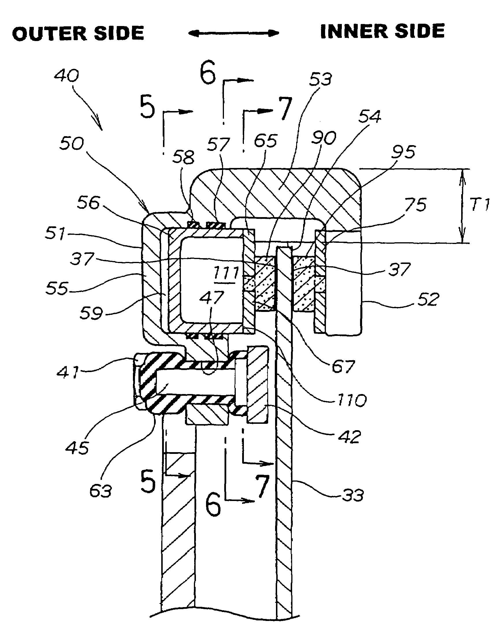
first embodiment
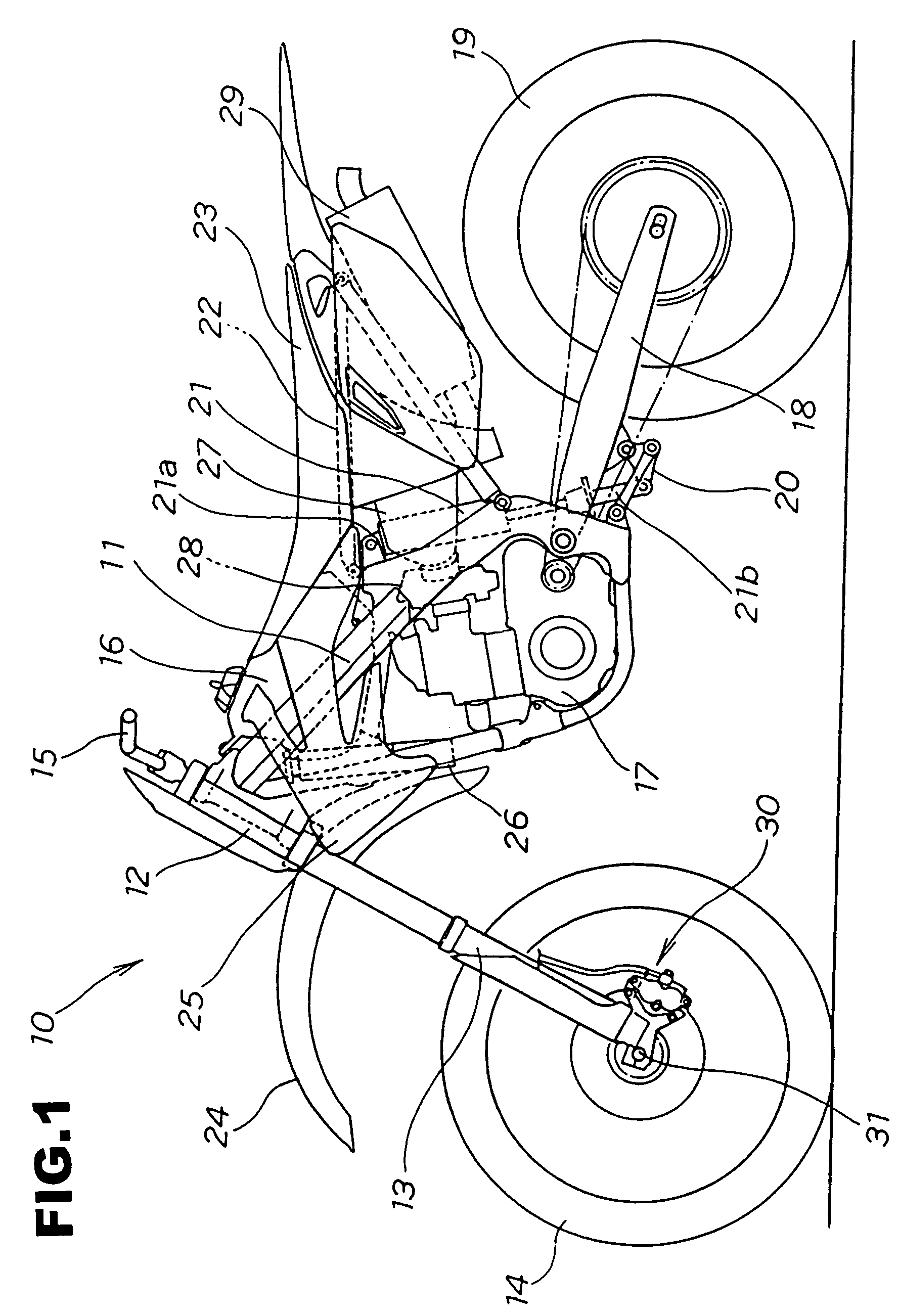
[0033]FIG. 1 is a side cross sectional drawing showing a motorcycle provided with the motorcycle disk brake unit (first embodiment) of the present invention.
[0034]The motorcycle 10 has a front fork 13 attached to a head pipe 12 of a vehicle frame 11, a front wheel 14 supported by the front fork 13, a handlebar 15 attached to the front fork 13, a fuel tank 16 attached to an upper part of the vehicle frame 11, an engine 17 attached below the fuel tank 16, a rear swing arm 18 attached in a swingable manner to a rear end of the vehicle frame 11, a rear wheel 19 attached to a rear part of this rear swing arm 18, a link mechanism 20 attached close to a front end of the rear swing arm 18, a lower part 21b of a rear cushion 21 attached to the link mechanism 20, an upper part 21a of the rear cushion 21 attached to a rear upper part of the vehicle frame 11, a rear frame 22 attached to a rear part of the vehicle frame 11, a seat 23 attached to an upper part of the rear frame 22, and a motorcyc...
second embodiment
[0098]A second embodiment will now be described.
[0099]FIG. 9 is a side view showing a motorcycle disk brake unit (second embodiment) of the present invention.
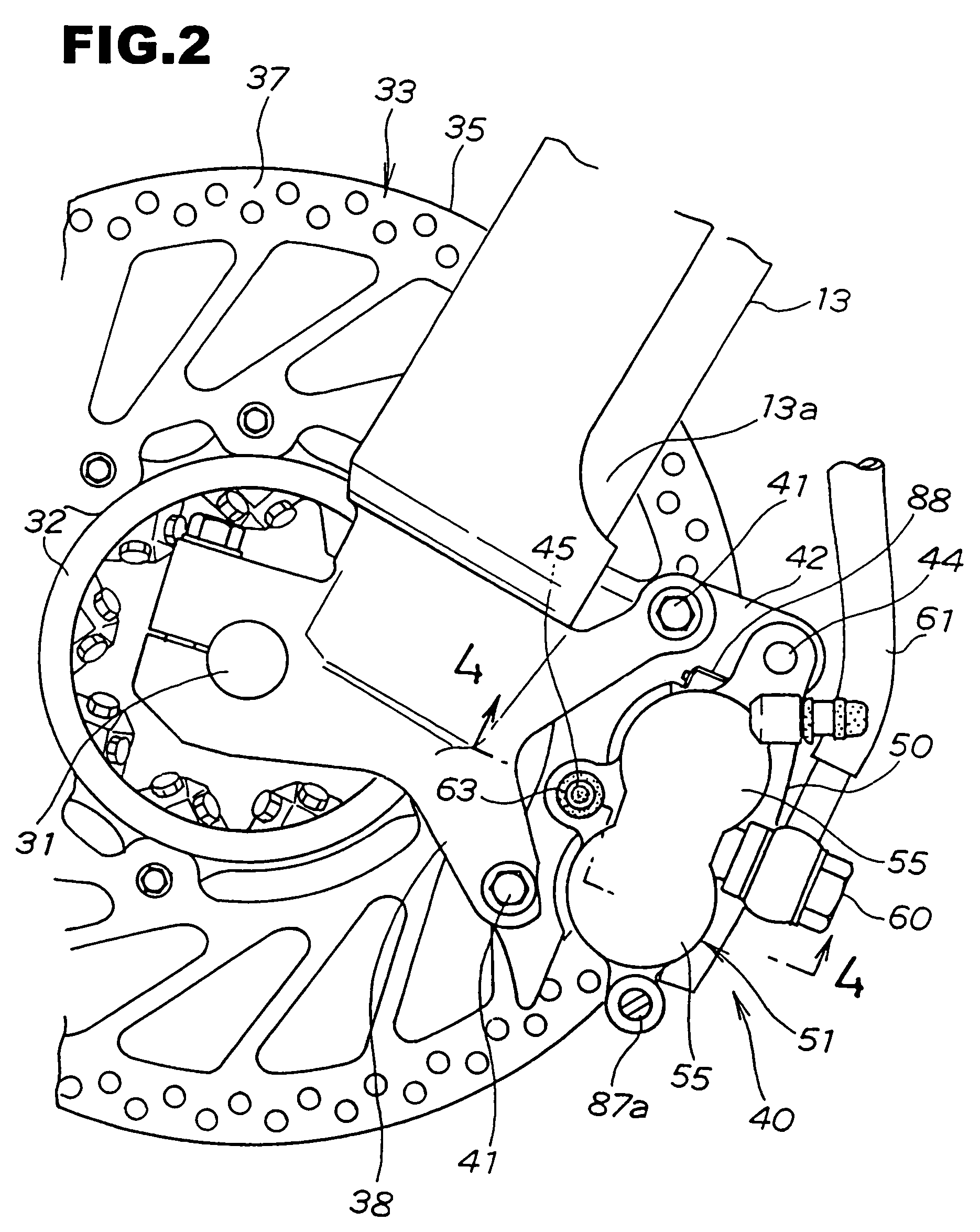
[0100]The motorcycle disk brake unit 120 of the second embodiment is provided with a brake disk 121 instead of the brake disc 33 of the motorcycle disk brake unit 30, and the remaining structure is the same as the first embodiment.
[0101]The brake disk 121 has indentations 123 . . . formed at specified intervals on the outer edge 122. By forming the indentations 123 . . . in the outer edge 122 it is possible to reduce the weight of the brake disk 121, and it is also possible to improve the design characteristics.
[0102]In the case of adopting this brake disk 121, a circumscribed circle (shown by a dotted line) 124 contacting the apex 122a of the outer periphery 122 is equivalent to the outer edge 35 (refer to FIG. 2) of the brake disc 33 constituting the first embodiment. Therefore, similarly to the motorcycle disk brake unit 30 ...
PUM
 Abstract
Description
Claims
Application Information