Carburization treatment method and carburization treatment apparatus

a treatment method and carburization technology, applied in heat treatment apparatus, furnaces, manufacturing tools, etc., can solve the problems of one gas carburization method, large amount of cosub>2 /sub>gas, explosion possibility, intergranular oxidation on the surface of steel materials,

Inactive Publication Date: 2007-10-02
DOWA THERMOTECH
View PDF6 Cites 12 Cited by
  • Summary
  • Abstract
  • Description
  • Claims
  • Application Information

AI Technical Summary

Benefits of technology

[0007]Accordingly, it is an object of the present invention to provide improved, new and economical carburization treatment methods which can be effectively used to replace any one of the above-described conventional carburization methods. It is another object of the present invention to provide an improved carburization treatment apparatus which is suitable for carrying out the carburization treatment methods provided according to the present invention.

Problems solved by technology

However, one gas carburization method has a disadvantage of the generation of a large amount of CO2 gas and a possibility of an explosion.
A further problem associated with this method is that intergranular oxidation will occur on the surface of the steel material.
On the other hand, another gas carburization method using an endothermic gas makes it necessary to employ a metamorphism furnace, hence suffering from a problem of high equipment cost.
A vacuum carburization method is associated with a problem in that once the carbon concentration on the surface of a steel material is increased to a predetermined solid solubility, a large amount of soot will be undesirably generated.
As a result, not only does the carburization equipment need a comparatively long time and a considerably high cost for maintenance, but also such equipment does not have sufficient versatility.
Moreover, another problem associated with this method is that it is difficult to perform a carbon potential control in an atmosphere within the furnace, if compared with the above-described gas carburization methods.
In addition, a plasma carburization method is said to be low in productivity.

Method used


Image

  • Carburization treatment method and carburization treatment apparatus
  • Carburization treatment method and carburization treatment apparatus
  • Carburization treatment method and carburization treatment apparatus

Examples


example 1

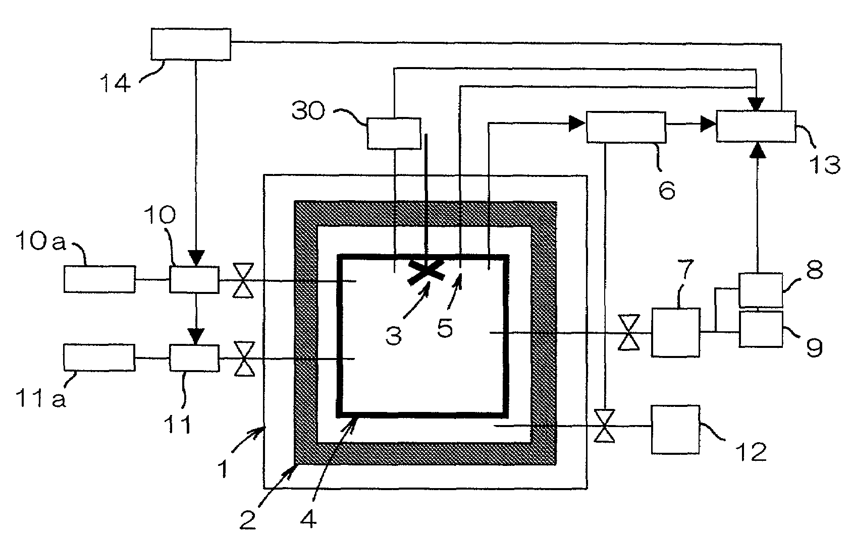
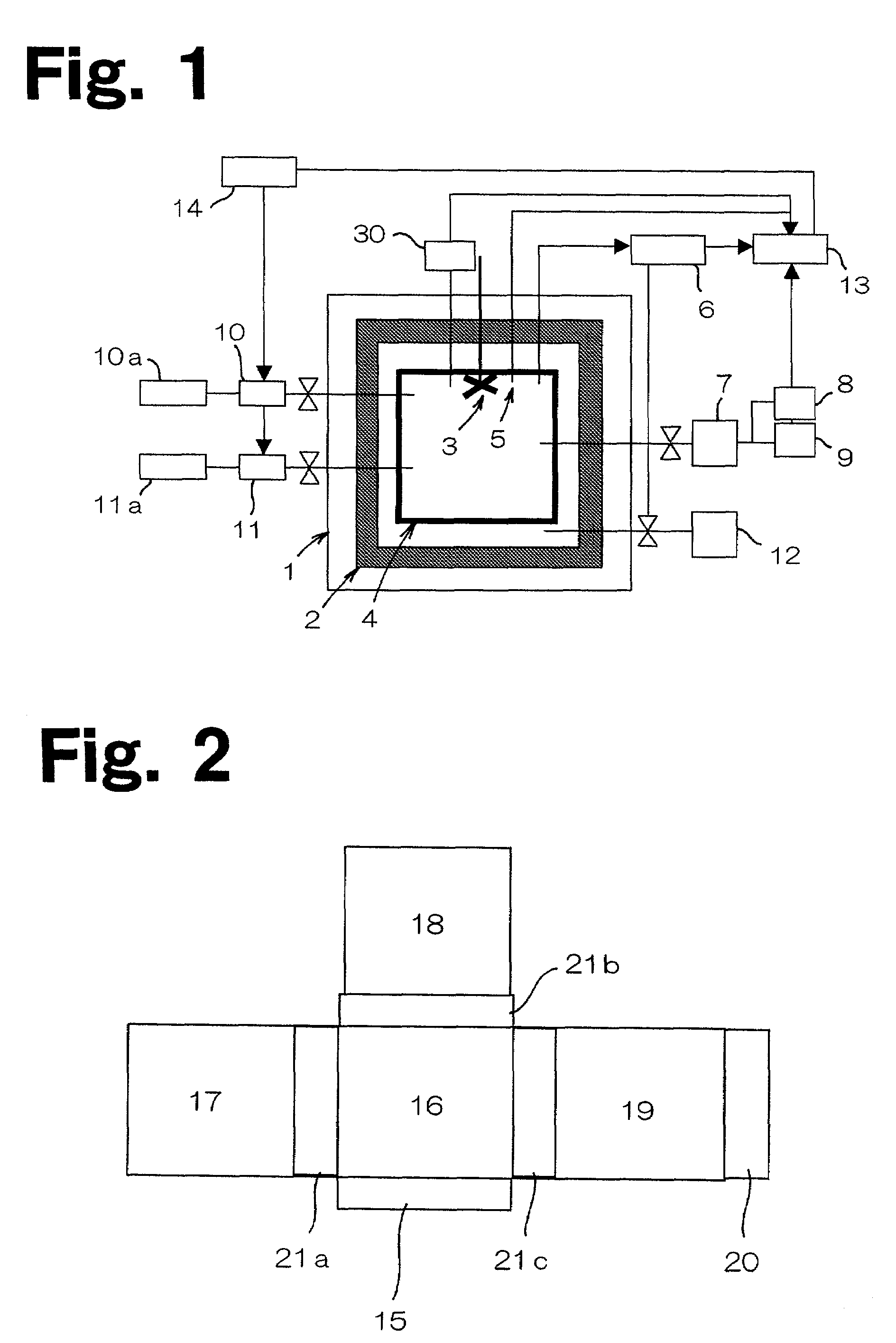
[0038]Sections of steel material SCM 420 in the form of test pieces each having a diameter of 20 mm and a length of 40 mm were disposed at nine positions (upper and lower corner portions as well as in the central area) within the carburization room 17 whose internal temperature was controlled at 950° C. and whose internal pressure was controlled at 0.1 kPa or lower. Then, the pressure within the carburization room 17 was restored to 100 kPa by charging the room with N2 gas, while the internal temperature thereof was kept at 950° C.

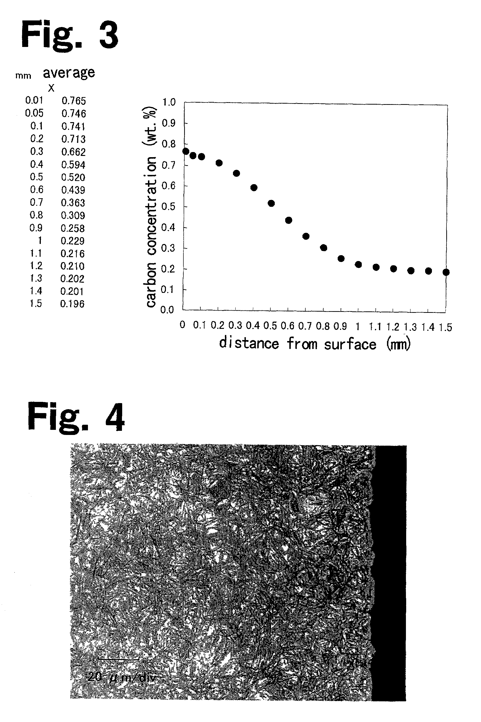
[0039]After the carburization room 17 had been kept under the above-described conditions for 30 minutes, its internal pressure was reduced to 0.1 kPa by virtue of gas discharge. Subsequently, C3H8 gas and CO2 gas were supplied into the carburization room 17, each at a flow rate of 3.5 L / min so as to increase the internal pressure to 1.7 kPa.

[0040]Next, with the internal pressure of the carburization room 17 kept at 1.7 kPa, the amount of C3H8 gas and / or CO...

example 2

[0044]Example 2 is used to explain how a high temperature carburization can be carried out. Namely, sections of steel material pieces which were identical to those used in Example 1 were disposed at nine positions within the carburization room 17 whose internal temperature was controlled at 1050° C. and whose internal pressure was controlled at 0.1 kPa or lower. Then, the pressure within the carburization room 17 was restored to 100 kPa by charging the room with N2 gas, while the internal temperature thereof was kept at 1050° C.

[0045]After the carburization room 17 had been kept under the above-described conditions for 30 minutes, its internal pressure was reduced to 0.1 kPa by virtue of gas discharge.

[0046]Subsequently, C3H8 gas and CO2 gas were supplied into the carburization room 17 at a flow rate of 14 L / min so as to increase the internal pressure to 1.7 kPa.

[0047]Next, with the internal pressure of the carburization room 17 kept at 1.7 kPa, the supply amount of CO2 gas was cont...

example 3

[0052]Example 3 was conducted based on Example 1 but using a different carburization pressure from that used in Example 1. Namely, sections of steel material pieces which were identical to those used in Example 1 were disposed at nine positions within the carburization room 17 whose internal temperature was controlled at 950° C. and whose internal pressure was controlled at 0.1 kPa or lower. Then, the pressure within the carburization room 17 was restored to 100 kPa by charging the room with N2 gas, while the internal temperature thereof was kept at 950° C.

[0053]After the carburization room 17 had been kept under the above described conditions for 30 minutes, its internal pressure was reduced to 0.1 kPa by virtue of gas discharge. Subsequently, C3H8 gas and CO2 gas were supplied into the carburization room 17, each at a flow rate of 15 L / min so as to increase the internal pressure to 100 kPa.

[0054]Next, with the internal pressure of the carburization room 17 kept at 100 kPa, the sup...


PUM

PropertyMeasurementUnit
pressureaaaaaaaaaa
internal pressureaaaaaaaaaa

Abstract

The invention provides a carburization treatment method in which a carburization treatment is conducted simultaneously with an operation of supplying a hydrocarbon gas and an oxidative gas into a furnace kept under a reduced pressure. Preferably, the internal pressure within the furnace is kept at 0.1 to 101 kPa, the hydrocarbon gas is one, two or more than two kinds of gases selected from the group consisting of C3H8, C3H6, C4H10, C2H2, C2H4, C2H6 and CH4, while the oxidative gas is an air, an O2 gas, or CO2 gas.

Description

BACKGROUND OF THE INVENTION[0001]1. Field of the Invention[0002]The present invention relates to carburization treatment methods for carburizing steel material and a carburization treatment apparatus suitable for carrying out the carburization treatment methods.[0003]2. Description of the Related Art[0004]Various methods are known for carburizing steel material, such as a gas carburization method, a vacuum carburization method, and a plasma carburization method, with each having both advantages and disadvantages.[0005]However, one gas carburization method has a disadvantage of the generation of a large amount of CO2 gas and a possibility of an explosion. A further problem associated with this method is that intergranular oxidation will occur on the surface of the steel material. On the other hand, another gas carburization method using an endothermic gas makes it necessary to employ a metamorphism furnace, hence suffering from a problem of high equipment cost.[0006]A vacuum carburiz...

Claims


Application Information

Patent Timeline
Patent Type & Authority Patents(United States)
IPC IPC(8): C21D1/74C23C8/20C23C8/22C23C8/28
CPCC23C8/22C23C8/20
Inventor EBIHARA, HISASHITAKAHASHI, JUNABUKAWA, FUMITAKAYOKOSE, KEIJIJURYOZAWA, HIDETOSHI
Owner DOWA THERMOTECH
Why Eureka
Try Eureka