Method and device for non-contact energy transmission

a non-contact energy and transmission method technology, applied in the direction of dc source parallel operation, constant-current supply dc circuit, electric variable regulation, etc., can solve the problems of high switching loss and the inability to maintain the synchronous principle, and achieve the effect of simple driving, low cost, and low cos

Inactive Publication Date: 2007-10-02
SEW-EURODRIVE GMBH & CO KG
View PDF10 Cites 8 Cited by
  • Summary
  • Abstract
  • Description
  • Claims
  • Application Information

AI Technical Summary

Benefits of technology

[0012]In accordance with an example embodiment of the present invention with respect to the device, the arrangement for driving the respective switch may include no arrangement for synchronization to the medium-frequency feed-ins. The driving may be simple, cost-effective and, in particular, robust with respect to interference effects in the case of asynchronously operating feed-ins.
[001

Problems solved by technology

However, an important disadvantage may be that this high switching frequency 2fM results in high switching losses.
Another disadvantage may be that t

Method used


Image

  • Method and device for non-contact energy transmission
  • Method and device for non-contact energy transmission
  • Method and device for non-contact energy transmission

Examples


Embodiment Construction

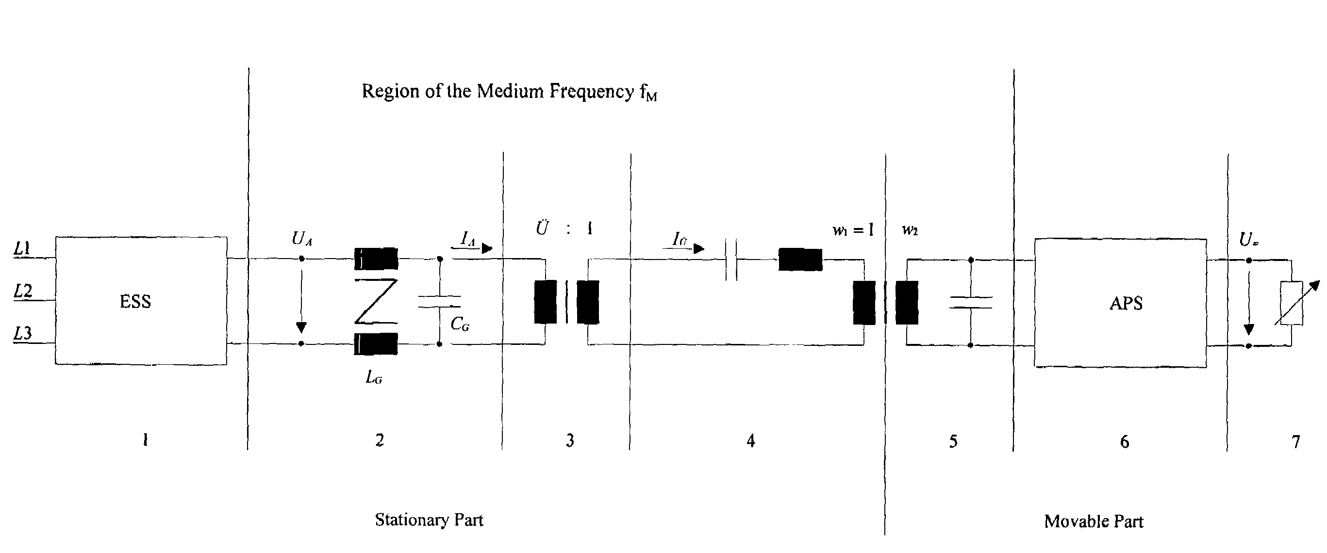
[0055]FIG. 1 is a first exemplary schematic diagram for non-contact energy transmission having a matching controller 6. The schematic diagram includes a stationary and a movable part.

[0056]The stationary part includes an infeed controller 1, a gyrator 2, a matching transformer 3 and a transmission line 4.

[0057]Infeed controller 1 converts the low-frequency AC voltage received from the three-phase system (L1, L2, L3) into a medium-frequency voltage UA having a constant medium frequency fM of, for example, 25 kHz. A resonantly operated series resonant circuit, so-called gyrator 2, connected in series to infeed controller 1, represents a voltage-controlled current source IA. Gyrator capacitance CG and gyrator inductance LG are rated or configured in accordance with medium frequency fM and the nominal power of infeed controller 1.

[0058]Current source IA feeds a matching transformer 3 whose transformation voltage ratio U is such that a medium-frequency current IU, which is constant in it...


PUM


Abstract

A method and a device for non-contact energy transmission from one or more medium-frequency current sources, whose medium frequencies may have deviations around fM, to one or more moving consumers via one or more transmission lines and from or via transformer heads, allocated to the moving consumers, having one or more downstream matching controllers for adjusting the power received from the transmission lines. The currents fed into a matching controller are brought together with the aid of a single switch, depending upon the power demand of the consumers connected to the matching controller. The switching frequency of the switch is selected as a fixed value from a 10%-wide tolerance band around 1/fM. The output voltages of a plurality of matching controllers are able to be parallel-connected via diodes for supplying a consumer.

Description

FIELD OF THE INVENTION[0001]The present invention relates to a method and a device for non-contact energy transmission.BACKGROUND INFORMATION[0002]German Published Patent Application No. 197 35 624 describes a method for the non-contact transmission of electric power from a medium-frequency current source having a medium frequency fM to one or more moving consumers via a transmission line, and from or via transformer heads, allocated to the moving consumers, having a downstream matching controller for adjusting the power received from the transmission line, the transmission line being fed from the medium-frequency current source with a medium-frequency current that is constant in its effective value during power transmission.[0003]The matching controller converts the medium-frequency current, injected from the transformer head, into a DC voltage. As described in FIGS. 3, 7a and 7b and the associated specification of German Published Patent Application No. 197 35 624, switch Ts is op...

Claims


Application Information

Patent Timeline
IPC IPC(8): H02J3/10H02J3/38H02J5/00H02M3/158
CPCH02J5/005H02M3/1584H02M1/44H02J50/12
Inventor UHL, THOMAS
Owner SEW-EURODRIVE GMBH & CO KG
Why Eureka
Try Eureka