Moving coil actuator for reciprocating motion with controlled force distribution

a technology of moving coils and actuators, applied in the field of scanning systems, can solve the problems of limited peak current density, temperature rise, and heat accumulation, and achieve the effects of reducing coil resistance, reducing peak current, and increasing peak curren

Inactive Publication Date: 2007-10-09
BIO RAD LAB INC
View PDF17 Cites 13 Cited by
  • Summary
  • Abstract
  • Description
  • Claims
  • Application Information

AI Technical Summary

Benefits of technology

[0010]These and other limitations of the prior art are addressed by the present invention, which resides in a moving coil actuator whose construction includes a magnet assembly with a gap within which are one or more regions of limited length in which magnetic flux is concentrated, plus a coiled electric conductor that has two coil regions separated either by no coil or by a coil of lower winding density than either of the two coil regions. The gap is large enough to receive the coiled electric conductor, either in whole or in part, with sufficient clearance to allow the conductor to travel back and forth within the gap, such that at each end of the length of travel one of the two coil regions is within a concentrated flux region and the other is not within a concentrated flux region. One of the two coil regions is thus exposed to a concentrated magnetic flux at one end of the length of travel and the other coil region is similarly exposed to a concentrated magnetic flux at the other end. The combined effect of concentrating the magnetic flux to a region of limited length and using two electric coils separated along the direction of travel provides the unique result of allowing the actuator to apply a maximal motor force to the payload at the ends of the stroke and a minimal motor force at the midpoint between the two ends.
[0012]An advantage offered by all embodiments of this invention is that the magnetic field generated by expensive field-producing materials, including permanent magnets and magnetic flux-conducting metals, is maximized and focused in regions where the highest forces are needed. The extra coil windings and / or magnetic material, included in actuators of the prior art to maintain a linear force response to the applied current, are now removed. This lowers the resistance of the coils as seen at the power supply, thereby allowing for higher peak currents, and it allows the system to limit the generation of force and power to locations where they are most needed. The weight of the actuator components, the power consumption, and the cost are all reduced relative to the prior art. This invention also allows the two coils to be energized individually at different times, i.e., each for only half the time that current is needed. A still further advantage is the ability to use a relatively small amount of magnetic material to achieve flux concentration in a region (or regions) of limited length within the gap. A still further advantage is the ability to leave one or both of the coil regions uncovered for a significant portion of the stroke, thereby allowing greater heat dissipation and higher peak current density. Still further advantages, embodiments, features, and objects of the invention will be apparent from the description that follows.

Problems solved by technology

The peak current density is limited by thermal considerations arising from heating of the coil, since electrical resistivity in the coil rises with increasing temperature, and increases in the current density cause the temperature to rise.
Heat accumulation is thus detrimental to the efficiency of the actuator.
Heat can also cause dimensional distortion of the attached payload, and when the payload contains optical components, this can destroy optical alignment.
Another factor affecting the efficiency of a moving coil actuator is the size and strength of the magnet.
While the underhung and overhung configurations achieve these goals, each has its limitations.
The underhung configuration requires a relatively large amount of magnetic material, which is a major component of the cost of the actuator.
In addition, the added coil length presents greater resistance to the electric current, thereby requiring a higher voltage and causing more resistance heating to occur within the coil.
One of the difficulties with scanners in general is that the greatest driving force is needed at the ends of the stroke, i.e., the extreme ends of the linear scanner travel path, where the direction of the scanner is reversed.
Accordingly, while conventional moving coil actuators are linear, i.e., the force that they generate is proportional to the current applied to the coil, this linearity is neither essential nor desirable.

Method used


Image

  • Moving coil actuator for reciprocating motion with controlled force distribution
  • Moving coil actuator for reciprocating motion with controlled force distribution
  • Moving coil actuator for reciprocating motion with controlled force distribution

Examples


Embodiment Construction

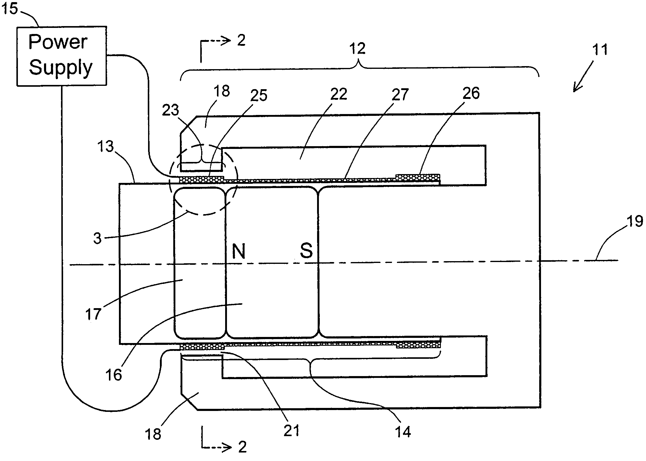
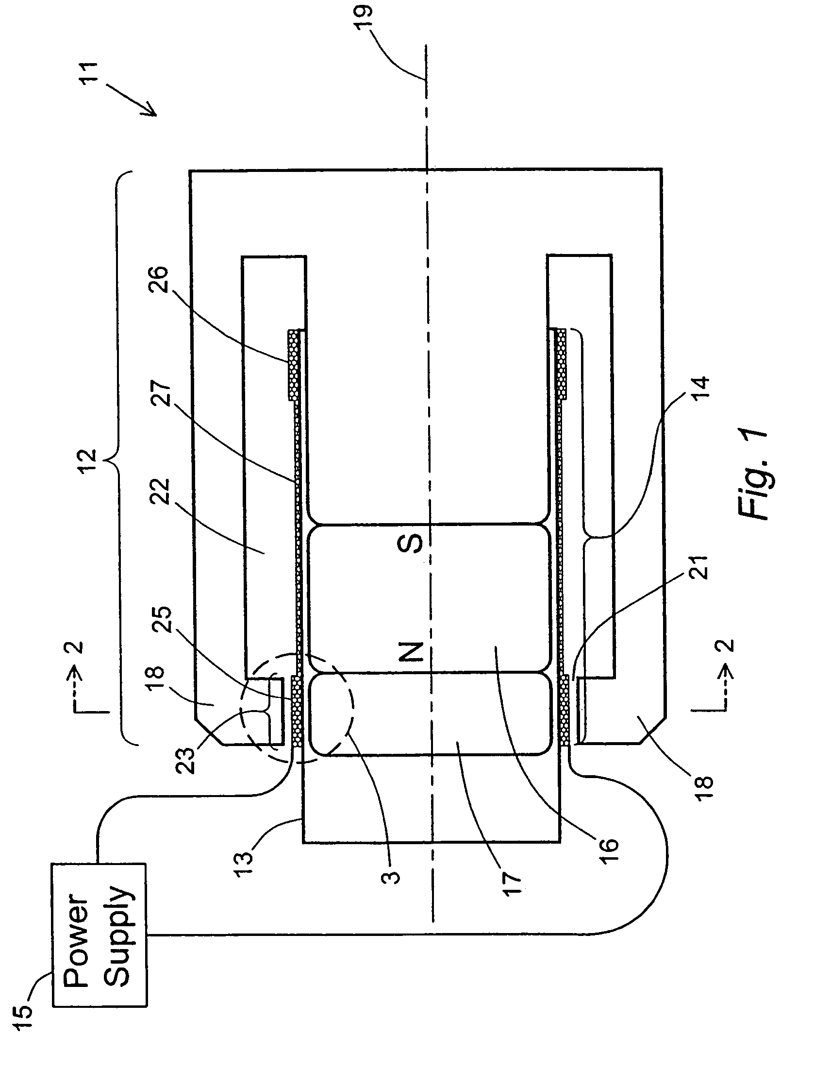
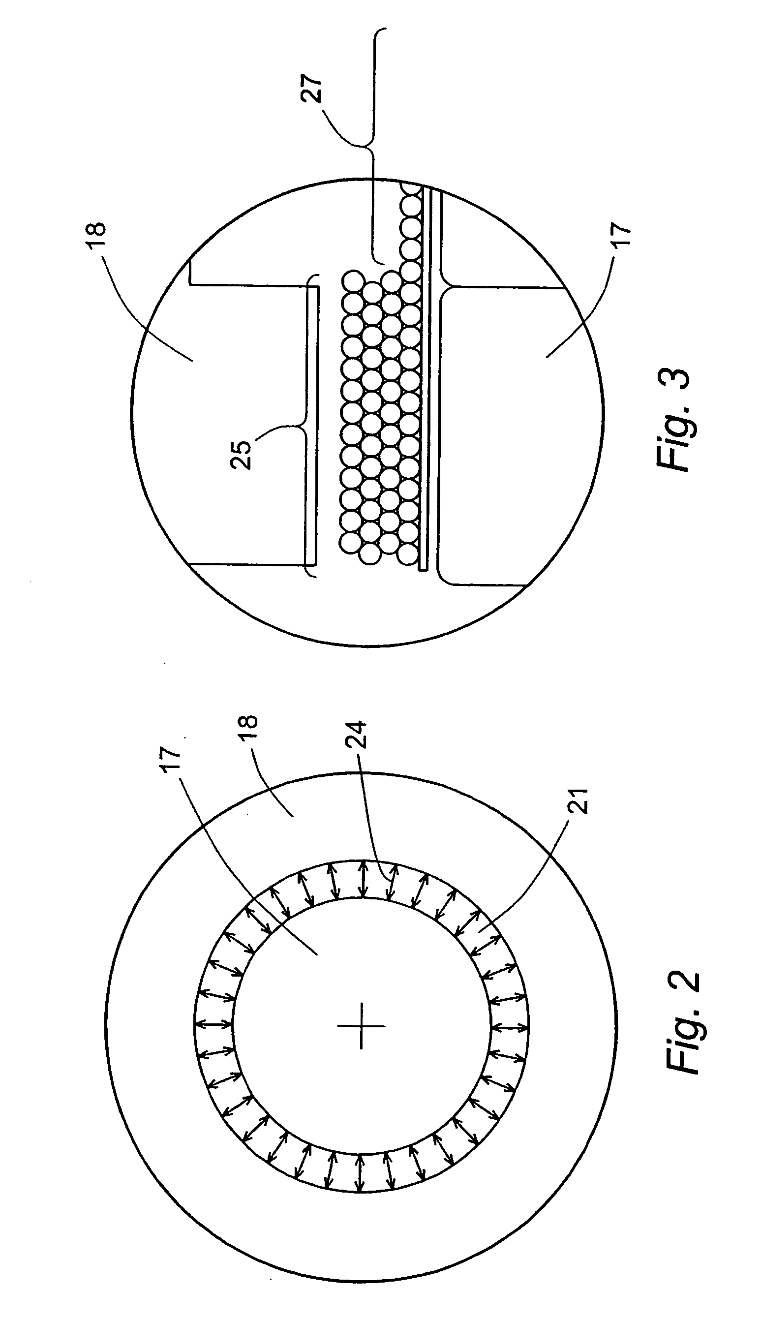
[0022]The electric coil portion of an actuator of the present invention includes two electric coil regions that are spatially separated, with either no coil between them or a coil of lower winding density than that of either of the two coil regions. In either case, the Lorentz force generated in the region separating the two electric coil regions is either zero or substantially and significantly lower than the Lorentz forces generated in the coil regions when those regions are in areas of concentrated magnetic flux. The expression “no coil” denotes either the absence of any electrical connection between the two coil regions or the presence of an uncoiled electrical connection, such as a straight connecting wire, that has at most a negligible effect on the motor force of the actuator. When the two coil regions are separated by a coil of lower winding density, the Lorentz force generated in the connecting region is again substantially lower than the Lorentz forces generated in the mor...


PUM


Abstract

A moving coil actuator that moves in a rapid back-and-forth motion is constructed with a magnet assembly that concentrates the magnetic flux in a region of limited length and with a coiled electric conductor that includes two separated regions of densely wound coil, the assembly and conductor arranged such that only one of the coil regions resides in a concentrated flux region at either end of the actuator stroke. This is achieved with either a single region of concentrated flux or two spatially separated regions of concentrated flux. In either case, the force constant, i.e., the motor force generated in each coil per unit of current through the coil, is non-linear, with a maximal force at each end of the stroke and a minimal force at the stroke mid-point. The result is an efficient use of the electric current and relatively small amounts of materials of construction, and accordingly less weight for the actuator to carry during its travel and its changes of direction.

Description

BACKGROUND OF THE INVENTION[0001]1. Field of the Invention[0002]This invention relates to scanning systems for microarrays of biological species such as nucleic acids or proteins, and for any type of procedure or analysis where very rapid illumination, observation, and / or detection is performed at a large number of individual sites arranged in a regular two-dimensional array. In particular, this invention relates to moving coil actuators as a driving mechanism for reciprocating motion of an optical system.[0003]2. Description of the Prior Art[0004]Microarrays are two-dimensional arrays of sites that are often of microscopic dimensions, with a different molecular species adhered to each site. These arrays are placed on glass slides, microtiter plates, membranes, and other two-dimensional supports, and one of their widest uses is in binding assays for the identification or characterization of an unknown biological species or the analysis of a sample for its inclusion of species that h...

Claims


Application Information

Patent Timeline
Patent Type & Authority Patents(United States)
IPC IPC(8): H02K33/00
CPCH02K33/18
Inventor PATT, PAUL J.CHU, DANIEL Y.CEREMONY, JEFFRY
Owner BIO RAD LAB INC
Why Eureka
Try Eureka