PFM control circuit for DC regulator

a control circuit and dc regulator technology, applied in the direction of dc-dc conversion, power supply, dc-dc conversion, etc., can solve the problems of linear voltage regulators due to power loss caused by passive regulating transistors, inferior switching voltage regulators, complicated circuitry, etc., and achieve broad loading and high efficiency.

Active Publication Date: 2007-10-09
GLOBAL MIXED MODE TECH
View PDF9 Cites 17 Cited by
  • Summary
  • Abstract
  • Description
  • Claims
  • Application Information

AI Technical Summary

Benefits of technology

[0007]In view of the above-mentioned problems, an object of the present invention is to provide a PFM control circuit capable of converting voltages with high efficiency over broad loading requirements.
[0009]The ON-time is adjusted in accordance with the current detection signal such that the ON-time is prolonged in response to an increase of a maximum of the current detection signal. Therefore, the necessary number of the switch cycles is prevented from increasing in a heavy loading operation, resulting in an improvement of the efficiency in voltage conversion. The OFF-time is adjusted in accordance with the voltage detection signal such that the OFF-time is prolonged in response to a reduction of a falling rate of the voltage detection signal. Therefore, the necessary number of the switch cycles is prevented from increasing in a light loading operation, resulting in an improvement of the efficiency in voltage conversion.

Problems solved by technology

In addition to the regulation of the power supply, the lifetime of the power supply is also an important issue to be considered for a variety of portable electronics devices powered by isolated and finite sources such as batteries.
In terms of the efficiency of voltage conversion, linear voltage regulators due to power loss caused by passive regulating transistors are inferior to switching voltage regulators.
However, the conventional control circuits and methods achieve a high efficiency of voltage conversion only within a limited range of loading requirements.
However, such a solution must combine two different kinds of control circuits into the same integrated circuit chip as well as a specially-designed mode selection circuit, resulting in complicated circuitry and a higher cost.

Method used


Image

  • PFM control circuit for DC regulator
  • PFM control circuit for DC regulator
  • PFM control circuit for DC regulator

Examples


Embodiment Construction

[0016]The preferred embodiments according to the present invention will be described in detail with reference to the drawings.

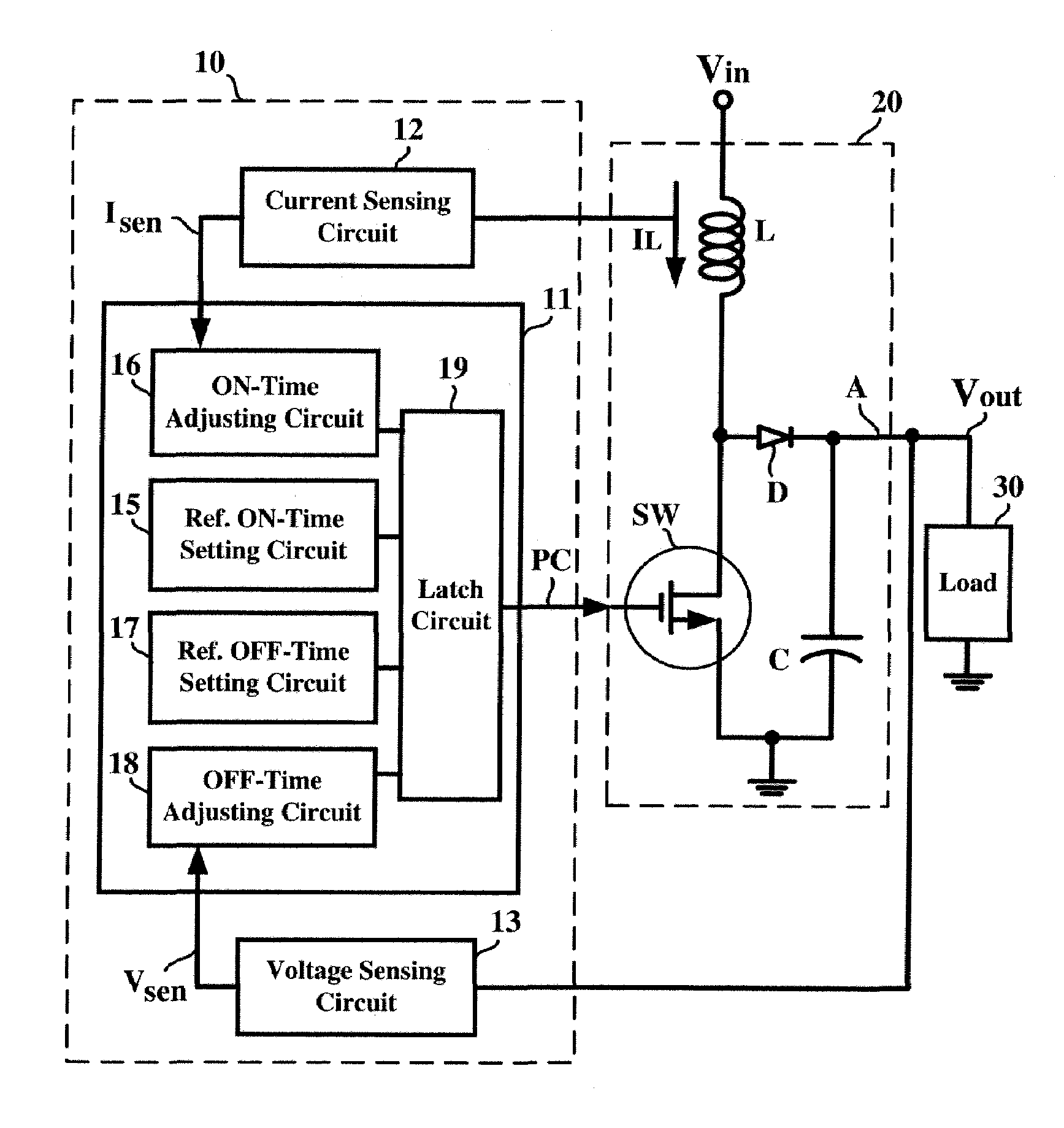
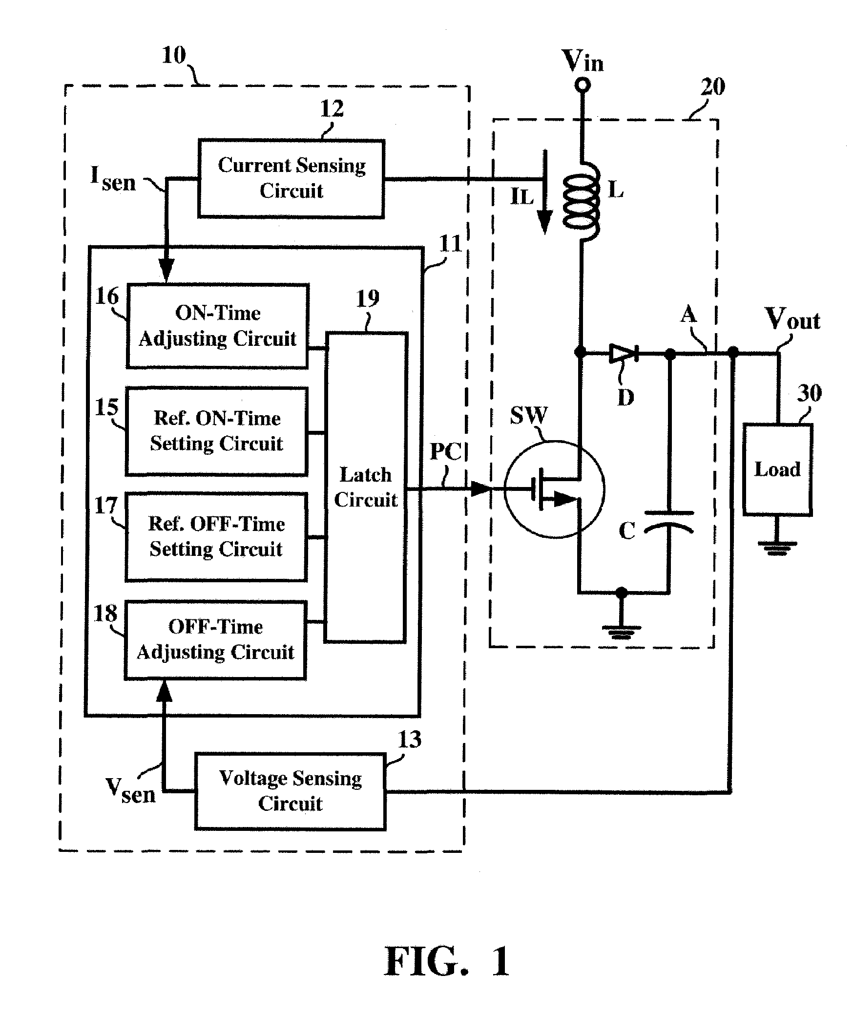
[0017]FIG. 1 is a circuit block diagram showing a PFM control circuit according to the present invention. Referring to FIG. 1, under control of a PFM control circuit 10, a switching regulator 20 is able to convert a susceptible input voltage Vin into a regulated output voltage Vout and supply a current required by a load 30 through an output terminal A. It should be noted that although the switching regulator 20 shown in FIG. 1 has a boost topology, the present invention is not limited to this and may be applied to a buck topology or any other topologies. Moreover, although the switching regulator 20 shown in FIG. 1 has a non-synchronous switching circuit consisting of a switching transistor SW and a diode D, the present invention is not limited to this and may be applied to a synchronous switching circuit consisting of two switching transistors.

[0018]The PFM...


PUM


Abstract

A PFM control circuit generates a pulse control signal for controlling a switching regulator to convert an input voltage into an output voltage. The pulse control signal has a plurality of switch cycles, each of which consists of an ON-time and an OFF-time. The ON-time is applied to turn on a switching circuit of the switching regulator while the OFF-time is applied to turn off the switching circuit. A current detection signal is representative of a current flowing through an inductive device of the switching regulator. The ON-time is prolonged in accordance with an increase of a maximum of the current detection signal. A voltage detection signal is representative of the output voltage. The OFF-time is prolonged in accordance with a reduction of a falling rate of the voltage detection signal.

Description

BACKGROUND OF INVENTION[0001]1. Field of the Invention[0002]The present invention relates to a pulse frequency modulation (PFM) control circuit and, more particularly, to a PFM control circuit for converting voltages with high efficiency over broad loading requirements.[0003]2. Description of the Related Art[0004]For providing electronics devices with a stable power supply so as to ensure steady performance, voltage regulators are indispensable components. The voltage regulator supplies a required amount of current to a load at a regulated output voltage. Therefore, when the electronics devices are used as the loads with respect to the voltage regulators, the performance of the electronics devices is kept stable and prevented from being affected by fluctuations of the power supply. In addition to the regulation of the power supply, the lifetime of the power supply is also an important issue to be considered for a variety of portable electronics devices powered by isolated and finite...

Claims


Application Information

Patent Timeline
Patent Type & Authority Patents(United States)
IPC IPC(8): G05F1/10
CPCH02M3/1563H03F3/2171H03F3/2175H03K7/06H03F2200/108H03F2200/462H03F2200/471H03F2200/75H03F2200/78H03F2200/348
Inventor TZENG, GUANG-NANCHEN, YUNG-CHIHTAIN, YA-DER
Owner GLOBAL MIXED MODE TECH
Why Eureka
Try Eureka