Magneto-optical device

a magneto-optical device and optical technology, applied in non-linear optics, instruments, optics, etc., can solve the problems of increasing the configuration complexity of the power supply unit, the inability to downsize, and the difficulty in speeding up the control of light, so as to reduce the driving voltage and the effect of downsizing the magneto-optical devi

Inactive Publication Date: 2007-10-09
KOHOKU KOGYO CO LTD
View PDF3 Cites 12 Cited by
  • Summary
  • Abstract
  • Description
  • Claims
  • Application Information

AI Technical Summary

Benefits of technology

[0017]The magneto-optical device according to the first aspect of the present invention can be utilized in a variable optical attenuator or an optical switch. When the magneto-optical device is utilized in a variable optical attenuator, fixed magnetic field of a permanent magnet is not necessary, and by generating variable magnetic fields by utilizing electromagnets only, the magnetization direction can instantaneously be changed, whereby downsizing and speedup can be implemented. In addition, since the magnetization direction can arbitrarily be controlled, the range from −45° to +45°, instead of the range from 0° to 90°, can be utilized so that the required 90-degree variable amount in the Faraday rotation angle is obtained; therefore, also in that sense, the downsizing of components to be utilized can be achieved. When the magneto-optical device is utilized in an optical switch, by utilizing a magneto-optical element having a self-latching function, it is not required to utilize a semi-hard magnetic material as a magnetic-yoke material; therefore, the magnetic field generated through the coils and the magnetic yoke may be a critical mass for reversing the magnetization of the magneto-optical element, whereby it is possible to achieve downsizing, speedup, and reduction of power dissipation. Moreover, because the magnetic-optical device has a structure in which a leakage magnetic field is weak and magnetic fields converge only on the magneto-optical element, they do not interfere with one another even though a plurality of the magneto-optical devices are arranged side by side; therefore, an array configuration can readily be realized.[The Second Aspect of the Present Invention]
[0024]As is the case with the magneto-optical device according to the first aspect of the present invention described above, the magneto-optical device according to the second aspect of the present invention can be utilized as a Faraday rotator in a variable optical attenuator or an optical switch. Further, by generating magnetic fields by utilizing electromagnets only, without utilizing any fixed magnetic field of a permanent magnet, the magnetization direction can instantaneously be changed, whereby downsizing and speedup can be implemented. Since, regardless of the direction of the combined magnetic field, no large magnetic field is required, the coils can be downsized, whereby the driving voltage can also be reduced.
[0031]Further, according to the third aspect of the present invention, there is provided a magneto-optical device comprising: a magnetic yoke having a block-shaped base portion made of a semi-hard magnetic material and at least four pillar portions, made of a high-magnetic-permeability material, extending from the base portion to the vicinity of a space to be an open-magnetic-circuit space; coils wound around the pillar portions; and a magneto-optical element arranged in the open-magnetic-circuit space surrounded by the respective top-end portions of the pillar portions, wherein magnetic fields generated through the coils are applied to the magneto-optical element, in three or more directions. In the case of this configuration, the direction of the combined magnetic field applied to the magneto-optical element can be controlled so as to be in an arbitrary direction in a 3-dimentional space, and the magnetic direction can be maintained after the exciting currents are cut off.
[0032]As is the case with the magneto-optical devices according to the first and second aspects described above, the magneto-optical device according to the third aspect of the present invention can be utilized as a Faraday rotator in a variable optical attenuator, a variable optical splitter, or an optical switch. Further, fixed magnetic field of a permanent magnet is not required, therefore, by generating variable magnetic fields by utilizing electromagnets only, downsizing of the magneto-optical device can be implemented. Because, regardless of the direction of the combined magnetic field, no large magnetic field is required, the coils can be downsized, whereby the driving voltage can also be reduced.
[0033]Moreover, by controlling the directions and the values of the respective currents applied to the coils, the direction (the magnetization direction of the magneto-optical element) of the combined magnetic field formed in the open-magnetic-circuit space can be controlled to be in an arbitrary direction, whereby the Faraday rotation angle can arbitrarily be adjusted. Furthermore, by forming with a semi-hard magnetic material the tabular portion or the pillar portion of the magnetic yoke, even after the exciting currents are cut off, the direction of the combined magnetic field that remains in the open-magnetic-circuit space can be controlled so as to be in an arbitrary direction, whereby the Faraday rotation angle can be maintained so as to be in an arbitrary condition.

Problems solved by technology

The first issue to be solved by the present invention is that, in the case of a conventional magneto-optical device in which a permanent magnet and a electromagnet are combined, because a magnetic field generated by the permanent magnet always acts, it is necessary to increase the number of windings of a coil that forms a variable magnetic field or to increase an electric current to be supplied, whereby downsizing is impossible, and it is difficult to speed up the control of light.
The second issue to be solved by the present invention is that, even though the permanent magnet is simply replaced by the electromagnet, the complexity of the configuration of the power supply units is raised, and the control is rendered difficult.

Method used


Image

  • Magneto-optical device
  • Magneto-optical device
  • Magneto-optical device

Examples


embodiment 1

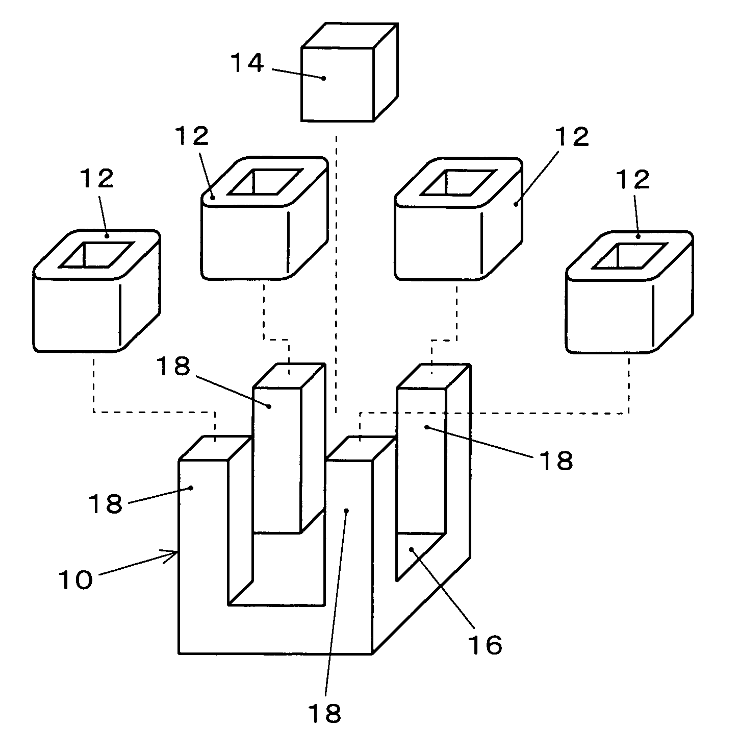
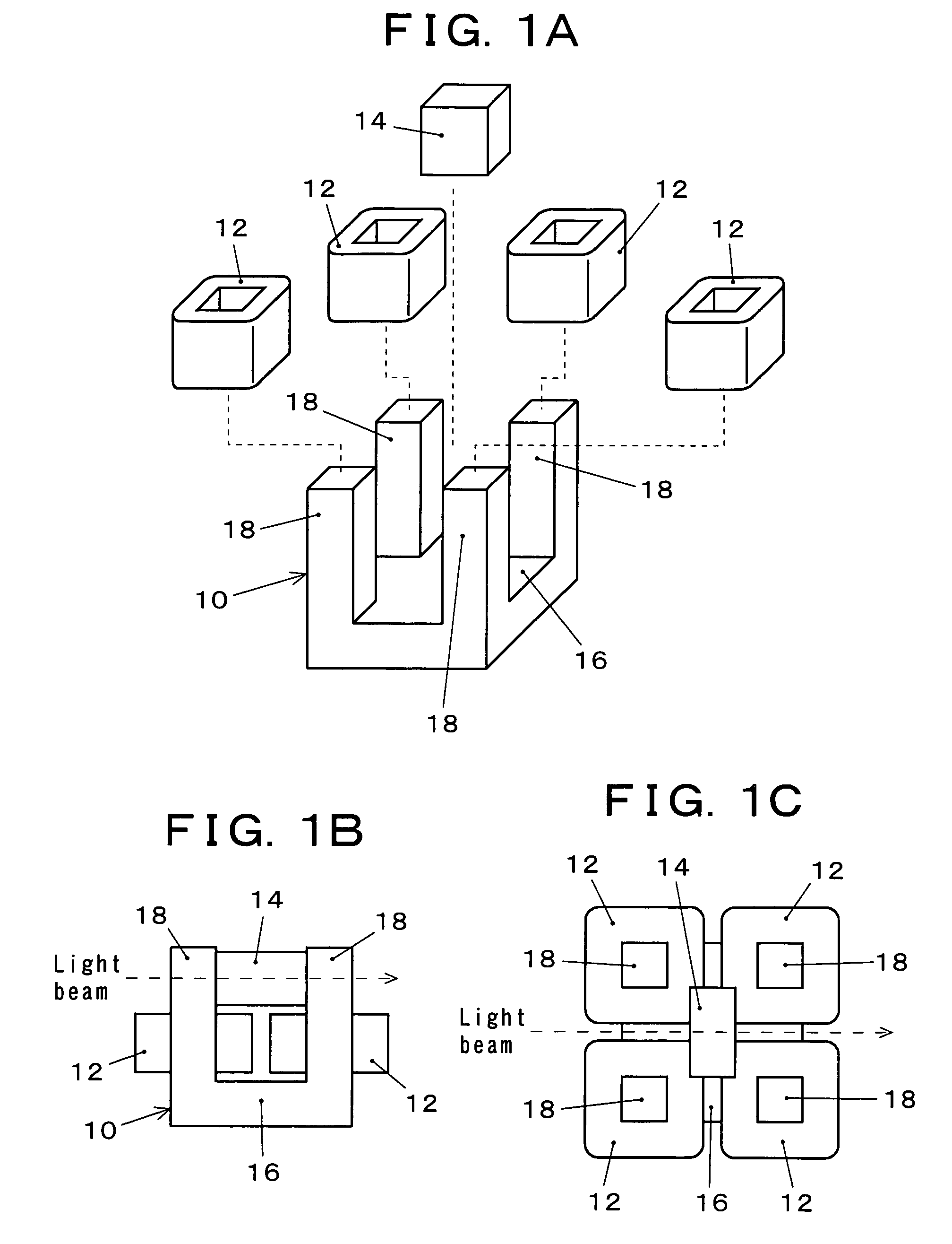
[0081]Embodiment 1 of a magneto-optical device according to the present invention will be explained with reference to FIGS. 1A to 5. In the case of the most simple configuration of a magneto-optical device in Embodiment 1, a single-piece magnetic yoke made of a high-magnetic-permeability material is utilized in which quadrangular pillar portions are protruding perpendicularly and identically oriented, from the vicinities of the four corners of a square tabular portion, respective coils are wound around the quadrangular pillar portions, and a magneto-optical element is arranged in an open-magnetic-circuit space surrounded by the top-end portions of the four quadrangular pillar portions. Besides, variable magnetic fields through the coils are applied to the magneto-optical element.

[0082]FIGS. 1A to 1C illustrate an example of a magneto-optical device according to the present invention. FIG. 1A is an exploded perspective view; FIGS. 1B and 1C are a side view and a plan view, respective...

embodiment 2

[0106]Embodiment 2 of a magneto-optical device according to the present invention will be explained with reference to FIGS. 6A to 19B. In the case of the most simple configuration of a magneto-optical device in Embodiment 2, as illustrated in FIGS. 6A to 6C, a single-piece magnetic yoke 114 made of a high-magnetic-permeability material is utilized in which quadrangular pillar portions 112 are protruding perpendicularly and in the same direction, from the vicinities of the four corners of a square tabular portion 110 (refer to FIG. 6A). Respective coils 116 are wound around the quadrangular pillar portions 112 (refer to FIG. 6B); a magneto-optical element 120 mounted on a non-magnetic holding member 118 is arranged in an open-magnetic-circuit space surrounded by the top ends of the four quadrangular pillar portions 112 (refer to FIG. 6C). Besides, the magneto-optical device is configured in such a way that variable magnetic fields generated through the coils 116 are applied to the ma...

embodiment 3

[0128]Embodiment 3 of a magneto-optical device according to the present invention will be explained with reference to FIGS. 20 to 28. As illustrated in FIG. 20, a magneto-optical device according to Embodiment 3 includes a magnetic yoke 210, coils 215 wound around the magnetic yoke 210, and a magneto-optical element 220. The magnetic yoke 210 has a configuration in which a disk-shaped tabular portion 211 and four inverted L-shaped pillar portions 212 protruding from a peripheral portion of the one surface of the tabular portion 211 are incorporated, the respective pillar portions 212 are arranged, along the circumference of the tabular portion 211, spaced approximately the same distance apart from one another, and the respective top ends of the pillar portions 212 are facing the center of the pillar portions 212. The tabular portion 211 is made of, e.g., a semi-hard magnetic material such as SUS420J2; the pillar portions 212 are made of a soft-magnetic material such as Mn—Zn-system ...


PUM

PropertyMeasurementUnit
angleaaaaaaaaaa
Faraday rotation angleaaaaaaaaaa

Abstract

It is possible to reduce the size of a magneto-optical device, increase the speed of optical control, simplify power supply structure and its control, and maintain a Faraday rotation angle in an arbitrary state even after shut-off of the excitation current. The magneto-optical device includes a magnetic yoke (10) made of a high-permeability magnetic material, the magnetic yoke including a tabular portion (16) and four pillar portions (18) protruding from one side of the tabular portion (16), a coil (12) wound on each of the pillar portions, and a magneto-optical element (14) arranged in an open-magnetic-circuit region surrounded by the end portions of the four pillar portions. A magnetic field obtained by a coil is applied to the magneto-optical element.

Description

TECHNICAL FIELD [0001]The present invention relates to a magneto-optical device utilized in a variable optical attenuator, an optical switch, or the like, and particularly to a magneto-optical device in which a magnetic yoke having at least three pillar portions protruding from a tabular portion is utilized, and the magnetization direction of a magneto-optical element is controlled by a magnetic field generated through coils wound around the columnar portions.BACKGROUND ART [0002]In an optical communication system, an optical measurement system, and the like, a variable optical attenuator is incorporated that is a device for variably controlling the transmitted optical power. The device is comprised of a magneto-optical element having the Faraday effect, a permanent magnet that applies a fixed magnetic field to the magneto-optical element, and an electromagnet that applies a variable magnetic field to the magneto-optical element. Typically, the electromagnet is of a structure in whi...

Claims


Application Information

Patent Timeline
Patent Type & Authority Patents(United States)
IPC IPC(8): G02F1/09
CPCG02F1/09G02F1/093
Inventor GOTO, YUJIKITAOKA, MIKIOUMEZAWA, HIROMITSUTOKUMASU, TSUGIOWATANABE, TOSHIHIKOMESAKI, AKITOSHIKATO, TAKASHIHOSHIKAWA, MASAHARUNISHIDA, CHIHARU
Owner KOHOKU KOGYO CO LTD
Why Eureka
Try Eureka