
Asynchronous pattern

a technology of asynchronous pattern and asynchronous method, applied in the field of asynchronous method calling, can solve the problems of consuming system resources, thread blocking, and negatively affecting system performan

Inactive Publication Date: 2007-10-09
MICROSOFT TECH LICENSING LLC
View PDF21 Cites 22 Cited by
  • Summary
  • Abstract
  • Description
  • Claims
  • Application Information

AI Technical Summary

Benefits of technology

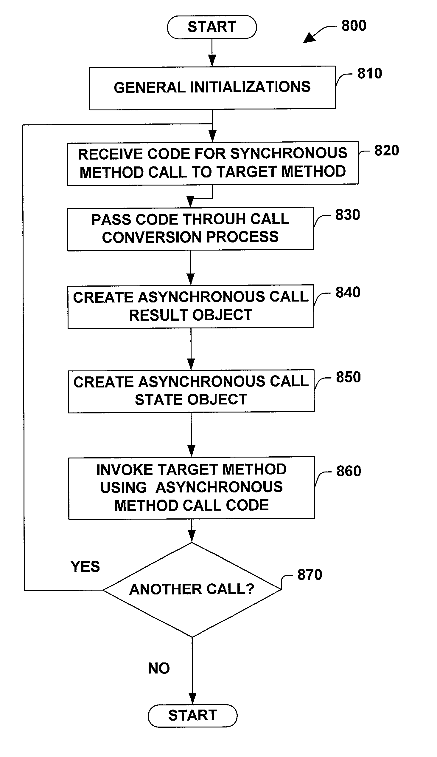
The present invention provides a system and method for converting synchronous calls to asynchronous calls using a common pattern. This pattern breaks a regular synchronous call into constituent parts, including but not limited to, a begin operation, an end operation, and a result / state object. The system and method allow a caller to determine whether a particular call should be asynchronous without requiring the called object to perform additional programming to support the asynchronous behavior of a calling client. Threads that employ the present invention to make asynchronous calls have options available for monitoring completion of the asynchronous operation, such as polling a property in the state object to determine whether asynchronous operation has completed, attempt to complete the operation prematurely (and thereby block until the operation completes), wait on a result object where periodic timeouts can be employed to wakeup and monitor the result, and performing the operation inside an asynchronous callback routine (executed by the called object when the operation is finished). The present invention makes it more likely that programmers will expend the time and energy to learn the asynchronous pattern. Overall, the invention provides an efficient model to employ asynchronous operations in various application environments.

Problems solved by technology

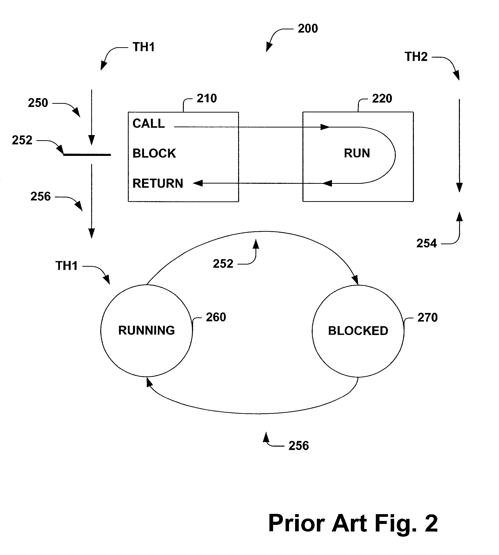
Conventionally, synchronous method calls can cause a thread to block.
This can negatively impact system performance.
Similarly, if ten separate threads are employed to make the ten synchronous calls, ten threads may be blocked, consuming system resources and again negatively impacting system performance.

Method used


Image

  • Asynchronous pattern
  • Asynchronous pattern
  • Asynchronous pattern

Examples


Embodiment Construction

[0029]The present invention is now described with reference to the drawings, wherein like reference numerals are used to refer to like elements throughout. In the following description, for purposes of explanation, numerous specific details are set forth in order to provide a thorough understanding of the present invention. It may be evident, however, that the present invention may be practiced without these specific details. In other instances, well-known structures and devices are shown in block diagram form in order to facilitate describing the present invention.

[0030]As used in this application, the term “component” is intended to refer to a computer-related entity, either hardware, a combination of hardware and software, software, or software in execution. For example, a component may be, but is not limited to being, a process running on a processor, a processor, an object, an executable, a thread of execution, a program, and a computer. By way of illustration, both an applicat...


PUM


Abstract

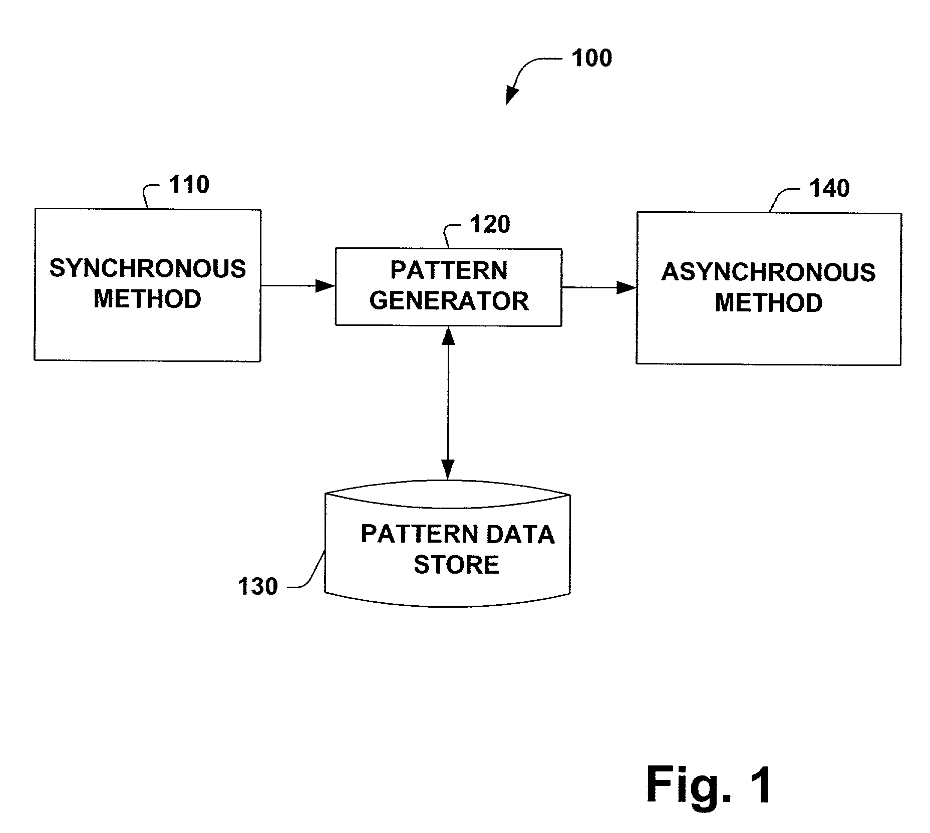
A system and method for converting code associated with synchronous method calls to code that can be employed to perform asynchronous method calls and for supporting such asynchronous method calls is provided. The system includes a pattern generator that can break code for a synchronous method call into one or more constituent parts including a begin asynchronous operation method, an end asynchronous operation method, an asynchronous call state object and an asynchronous call result object. The system includes a pattern data store that holds data associated with converting a synchronous method call to an asynchronous method call, which facilitates employing the system consistently across environments like file input / output, stream input / output, socket input / output, networking, remoting channels, proxies, web forms, web services and messaging message queues.

Description

TECHNICAL FIELD[0001]The present invention relates generally to asynchronous method calling and more particularly to a system and method for making asynchronous calls using a common pattern.BACKGROUND OF THE INVENTION[0002]Conventional synchronous method calls, where the caller blocks until the completion of processing performed by the callee, may provide unsatisfactory results in some calling situations. By way of illustration, if the callee takes a long time to complete, the caller may be blocked for an unacceptable period of time waiting for the callee to return. Thus, resources (e.g., memory, processor cycles) associated with a blocked caller thread may be unavailable for other threads, reducing system performance. By way of further illustration, if the caller desires to make multiple calls to one or more callees, where, from the caller's point of view, such calls can be performed substantially in parallel, conventional synchronous method calling techniques may generate an unwan...

Claims


Application Information

Patent Timeline
Patent Type & Authority Patents(United States)
IPC IPC(8): H04J3/16
CPCG06F9/4425G06F9/547Y10S707/99942Y10S707/99945Y10S707/99943G06F9/4484
Inventor GRUNKEMEYER, BRIAN M.HAWKINS, JONATHAN C.BRUMME, CHRISTOPHER W.KAKIVAYA, GOPALA KRISHNA R.OLSON, LANCE E.ROBSMAN, DMITRYSANDERS, II, HENRY L.
Owner MICROSOFT TECH LICENSING LLC
Learn More