
Method of spatially filtering a digital image using chrominance information

a digital image and chrominance information technology, applied in image enhancement, image analysis, instruments, etc., can solve the problems of overshoot and undershoot, unfavorable image tone scale characteristics, and large rendering of scene content, so as to improve the image tone scale characteristics

Active Publication Date: 2007-10-09
MONUMENT PEAK VENTURES LLC
View PDF16 Cites 30 Cited by
  • Summary
  • Abstract
  • Description
  • Claims
  • Application Information

AI Technical Summary

Benefits of technology

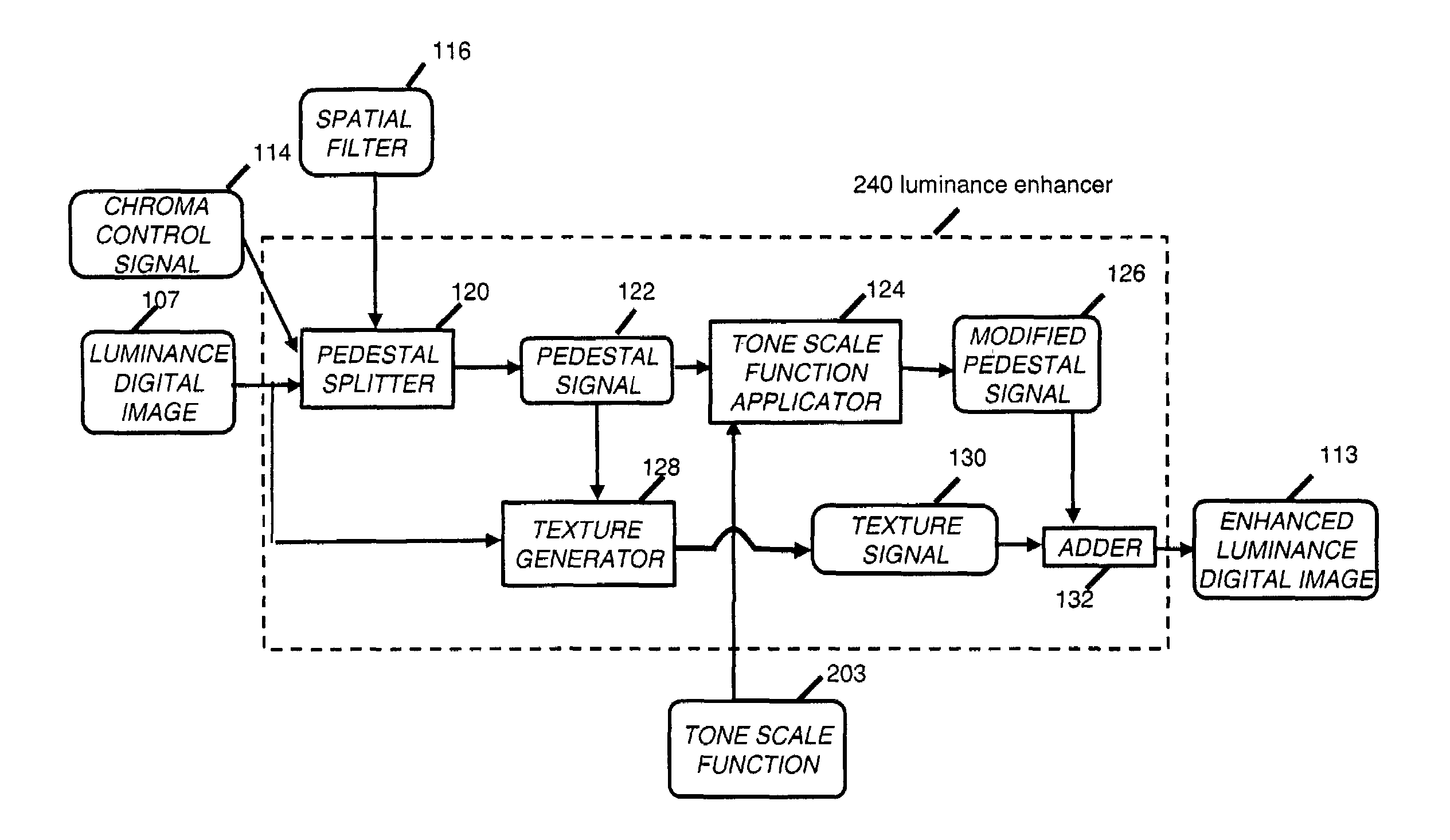
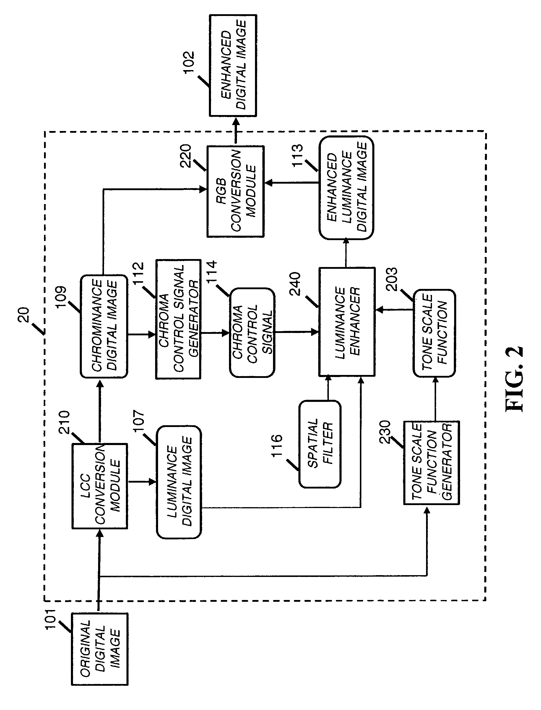
[0017]The need is met according to the present invention by providing a method of processing a color digital image having a luminance channel and one or more chrominance channels to improve the tone scale characteristics of the image that includes the steps of: producing a control signal from the one or more chrominance channels; generating a pedestal signal containing mainly low frequency modulation by filtering the luminance channel with a spatial filter, whereby the operation of the spatial filter is modulated by the control signal; and producing a texture signal by subtracting the pedestal signal from the luminance channel.

Problems solved by technology

The result of this incongruity is that a good deal of scene content is rendered to black or white on the output image.
This procedure preserves a segment of the image frequency spectrum, however, artifacts are seen at object boundaries in the image.
In addition, the preservation of high frequencies in the image may lead to the creation of unsharp mask type artifacts (overshoot and undershoot) in the neighborhood of large image edges (characteristic of large occlusion boundaries or dark shadows.)
In general, it was observed that larger digital filters (used to create the low-pass signal) result in a more pleasing processed image, except for the fact that the artifacts may become more objectionable.
This approach reduces the artifacts at edges, but diagonal edges pose a problem.
These methods are rather time consuming.
In addition, it has been found that optimal dynamic range modification cannot be realized by sensing edges at only a single resolution of the image.
A deficiency of this method is that the amplitude at each resolution does not adequately identify whether the signal is part of a large amplitude edge or an image texture.
However, it is often inconvenient to operate on the high frequency component of the multiple image resolution.
However the method taught by Burt et al. was designed for image compression applications and cannot be used for enhancing the tone scale of a digital image.
Thus, the prior art methods sometimes fail when the edges cannot adequately be determined by the luminance channel of an image alone.
In addition, the color information is not used to aid the filtering process when constructing the original fringe data.

Method used


Image

  • Method of spatially filtering a digital image using chrominance information
  • Method of spatially filtering a digital image using chrominance information
  • Method of spatially filtering a digital image using chrominance information

Examples


Embodiment Construction

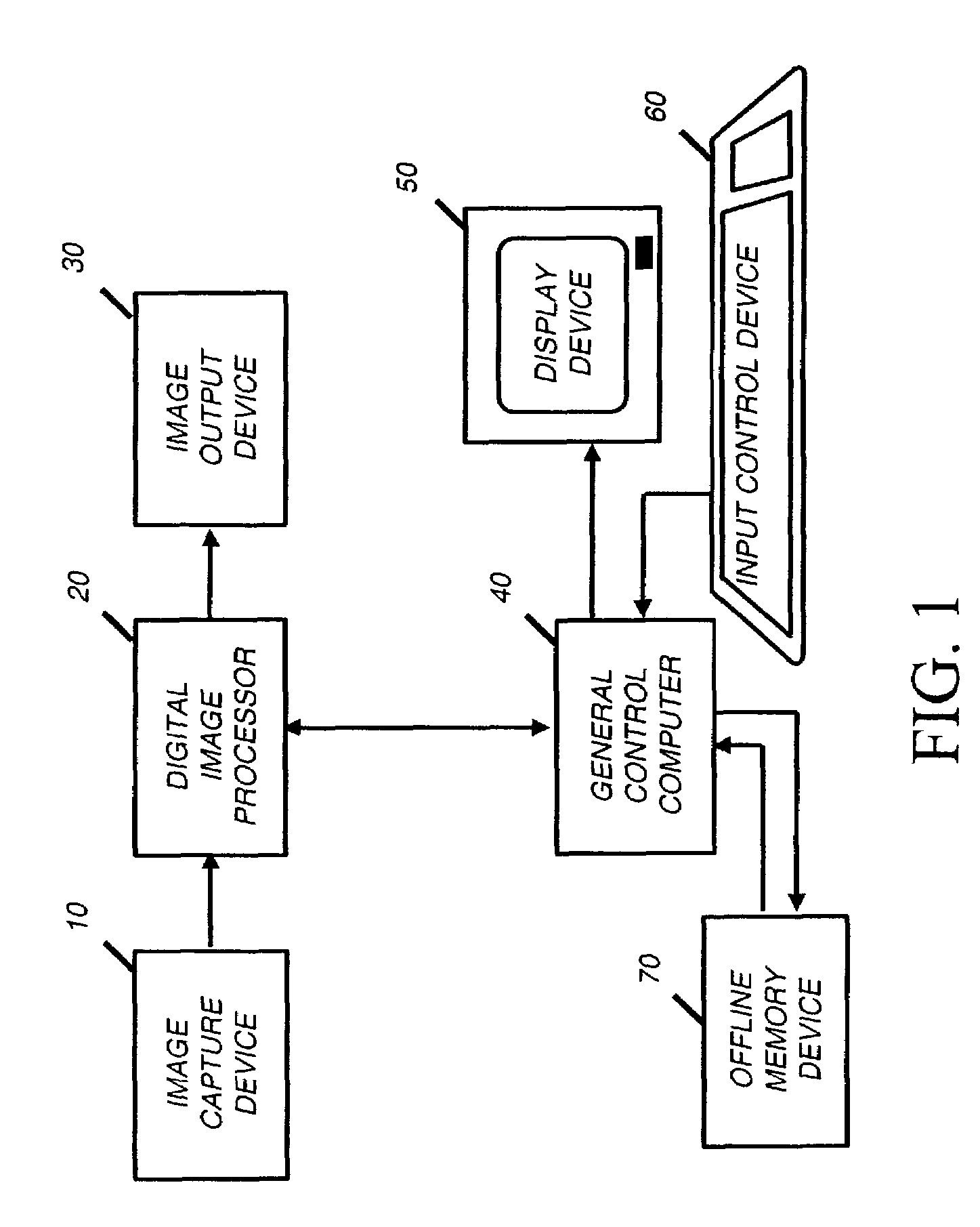
[0029]In the following description, a preferred embodiment of the present invention will be described as a software program. Those skilled in the art will readily recognize that the equivalent of such software may also be constructed in hardware. Because image manipulation algorithms and systems are well known, the present description will be directed in particular to algorithms and systems forming part of, or cooperating more directly with, the method in accordance with the present invention. Other aspects of such algorithms and systems, and hardware and / or software for producing and otherwise processing the image signals involved therewith, not specifically shown or described herein may be selected from such systems, algorithms, components, and elements known in the art. Given the description as set forth in the following specification, all software implementation thereof is conventional and within the ordinary skill in such arts.

[0030]The present invention may be implemented in c...


PUM


Abstract

A method of processing a color digital image having a luminance channel and one or more chrominance channels to improve the tone scale characteristics of the image, includes the steps of: producing a control signal from the one or more chrominance channels; generating a pedestal signal containing mainly low frequency modulation by filtering the luminance channel with a spatial filter, whereby the operation of the spatial filter is modulated by the control signal; and producing a texture signal by subtracting the pedestal signal from the luminance channel.

Description

FIELD OF INVENTION[0001]The present invention relates to an improved method of spatially filtering digital images.BACKGROUND OF THE INVENTION[0002]It is well known that the dynamic range of an image captured with an image capture device (such as a photographic negative) is often greater than the dynamic range of the output medium (such as a photographic paper or CRT monitor). The result of this incongruity is that a good deal of scene content is rendered to black or white on the output image. For this reason, in an image processing environment, a tone scale function may be used to reduce the scene dynamic range in order to map more information onto the output medium, in a process called dynamic range modification or dynamic range compression. The dynamic range compression modifies the tone scale characteristics of the image.[0003]There exist many processes for creating a tone scale function on an image dependent basis (e.g. see U.S. Pat. No. 5,471,987, issued Dec. 5, 1995 to Nakazaw...

Claims


Application Information

Patent Timeline
IPC IPC(8): G06K9/40G06K9/00G06T5/00G06T5/40
CPCG06T5/004G06T5/007G06T2207/20064G06T2207/20016G06T5/75G06T5/90
Inventor GALLAGHER, ANDREW C.GINDELE, EDWARD B.
Owner MONUMENT PEAK VENTURES LLC
Learn More