Eureka AIR delivers breakthrough ideas for toughest innovation challenges, trusted by R&D personnel around the world.

Optical signal multiplexer/demultiplexer employing pseudorandom mode modulation

Inactive Publication Date: 2007-10-09
AVAGO TECH WIRELESS IP SINGAPORE PTE
View PDF8 Cites 11 Cited by
  • Summary
  • Abstract
  • Description
  • Claims
  • Application Information

AI Technical Summary

Benefits of technology

[0011]This invention solves the above-cited problem by providing for the first time an optical signal multiplexer/demultiplexer employing an orthogonal pseudorandom (PRN) coding scheme for optical mode modulation to produce a plurality of independent optical signals that may be combined into one multiplex signal for transmission over an optical fiber to the receiving end, where the multiplex signal may be demultiplex

Problems solved by technology

Channel spacing is limited by many factors, including optical filter efficacy, frequency drift, interferometric crosstalk, fiber dispersion and nonlinearity.
The Hill et al. system uses simple coherent heterodyne detection to demultiplex the two signals and is admittedly impractical without additional (unspecified) polarization control techniques to compensate for the effects of PMD in fibers longer than a few thousand meters.
Evangelides et al. note that the polarization channel separation possible with solitons is not possible with other pulses.

Method used


Image

  • Optical signal multiplexer/demultiplexer employing pseudorandom mode modulation
  • Optical signal multiplexer/demultiplexer employing pseudorandom mode modulation
  • Optical signal multiplexer/demultiplexer employing pseudorandom mode modulation

Examples


Embodiment Construction

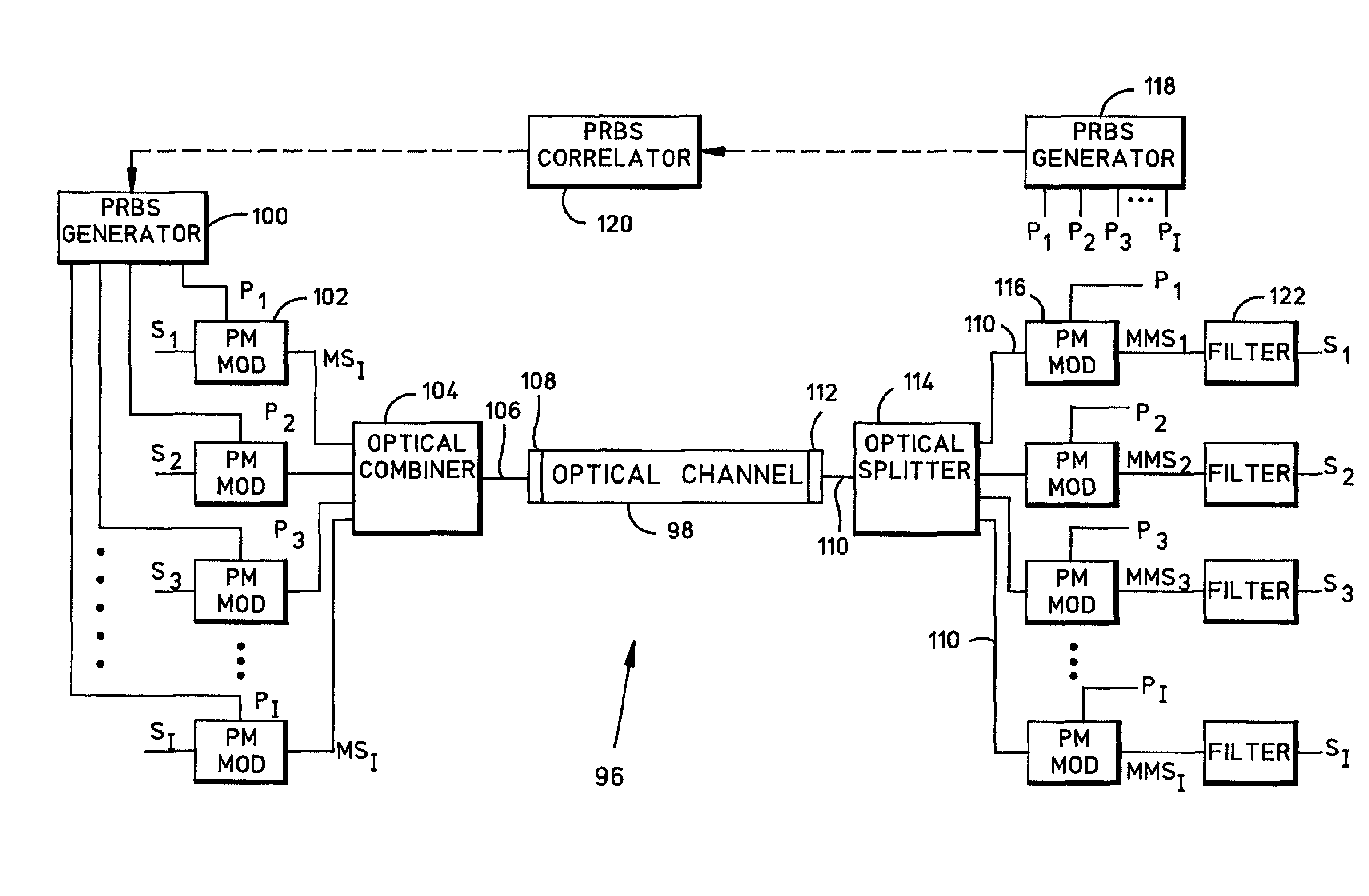
[0021]In a pseudorandom (PRN) coding scheme, the signal energy is spread over some signal parameter, such as phase or frequency, according to one of a set of data sequences that are statistically orthogonal. In the system of this invention, the signal energy is spread in an optical mode, such as polarization, before transmission over a common optical channel. Thus, several independent optical signals may each be spread in mode and combined for transmission over a single channel, as may be appreciated with reference to FIG. 1.

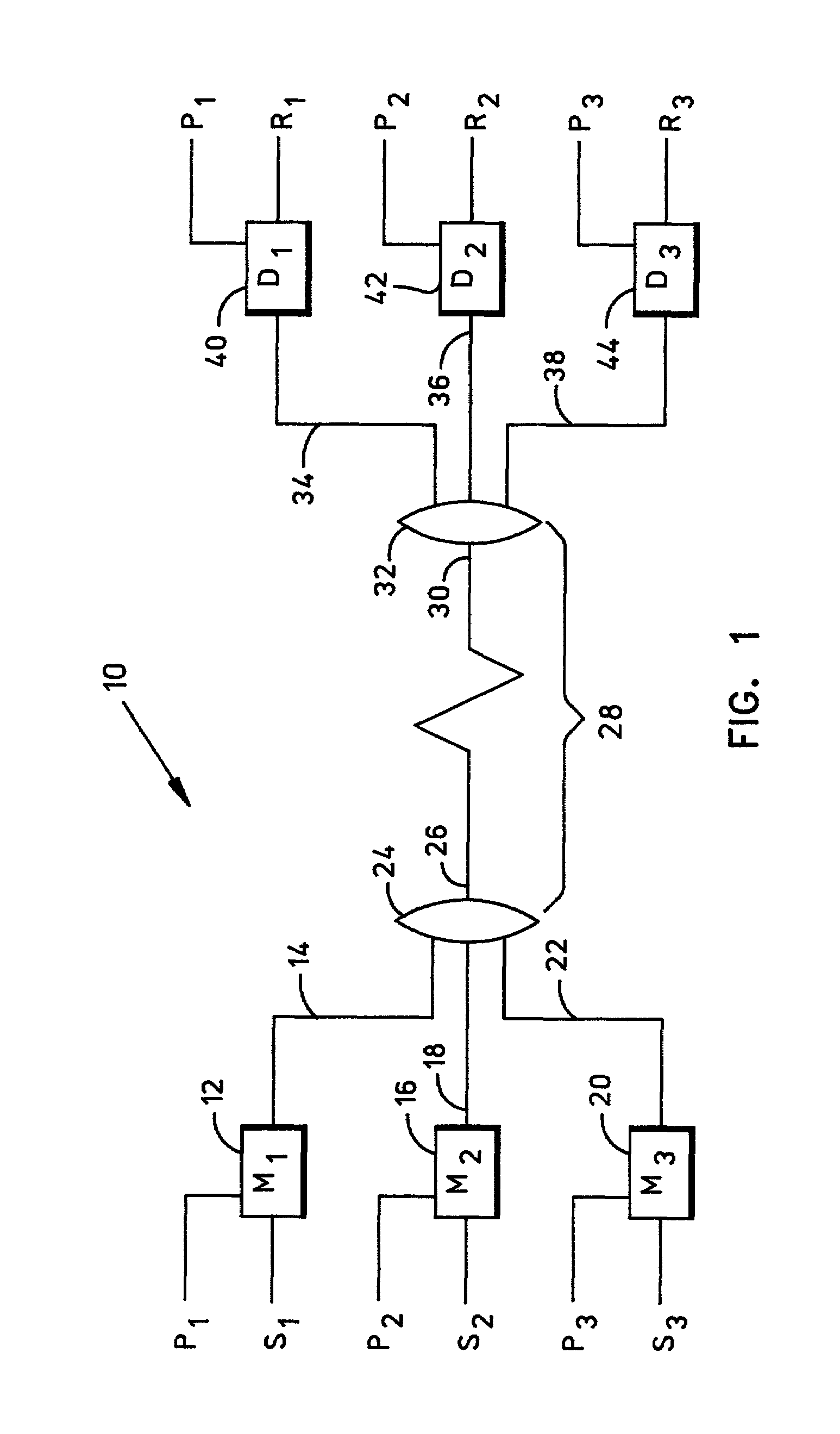
[0022]FIG. 1 is a schematic diagram illustrating the system 10 of this invention for transmitting a plurality (I) of independent optical signals {Si} through a single optical channel. Three independent optical signals S1, S2 and S3, each of which may be amplitude-modulated and of identical frequency and phase, for example, are shown coupled to separate mode modulators, which may include, for example, electro-optical polarizers. The three mutually orthogonal PRN ...


PUM


Abstract

An optical signal multiplexer / demultiplexer using an orthogonal pseudorandom (PRN) coding scheme for optical mode modulation to produce a plurality of independent optical signals that may be combined into one multiplex signal for transmission over an optical fiber to the receiving end, where the multiplex signal may be demultiplexed by relying on the orthogonal properties of the PRN code to isolate each independent optical signal from the transmitted multiplex signal. In channels subject to mode modulation distortion, one of the signal components may be used as a pilot signal to obtain a correction for channel mode modulation distortion. The PRN optical signal multiplexer / demultiplexer is particularly useful with polarization mode modulation.

Description

BACKGROUND OF THE INVENTION[0001]1. Field of the Invention[0002]This invention relates generally to optical signal processing and more particularly to an optical multiplexing apparatus employing pseudorandom bit sequence (PRBS) mode modulation.[0003]2. Description of the Related Art[0004]Optical networks using wavelength-division-multiplexing (WDM) and Dense WDM (DWDM) techniques have been installed throughout the world in response to increasing demand for communications channel capacity. Recent advances in WDM and DWDM technology have focused on improving capacity with either smaller channel wavelength spacing or wider wavelength range. Channel spacing is limited by many factors, including optical filter efficacy, frequency drift, interferometric crosstalk, fiber dispersion and nonlinearity. The art is replete with various multiplexing proposals for obtaining additional capacity in existing optical fiber systems.[0005]Some early practitioners proposed exploiting available WDM bandw...

Claims


Application Information

Patent Timeline
IPC IPC(8): H04B10/00H04B10/04H04B10/06H04B10/135H04B10/142H04B10/152
CPCH04B10/532
Inventor NISHIMURA, KEN A.SIMON, JONATHAN
Owner AVAGO TECH WIRELESS IP SINGAPORE PTE
Why Eureka
Eureka Blog
Learn More