Multi-thread execution method and parallel processor system
a parallel processor and multi-thread technology, applied in multi-programming arrangements, instruments, computation using denominational number representation, etc., can solve problems such as reducing processing efficiency, increasing processing volume, and reducing performance, so as to prevent an increase in hardware amount and increase overhead
- Summary
- Abstract
- Description
- Claims
- Application Information
AI Technical Summary
Benefits of technology
Problems solved by technology
Method used
Image
Examples
first embodiment
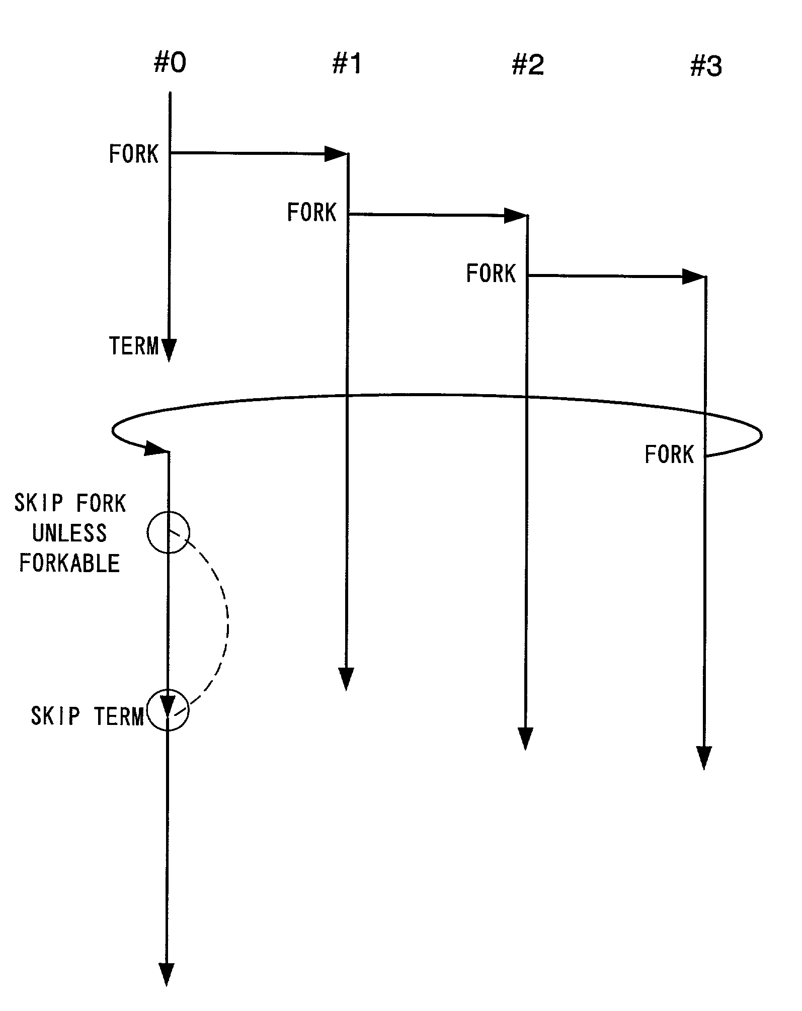
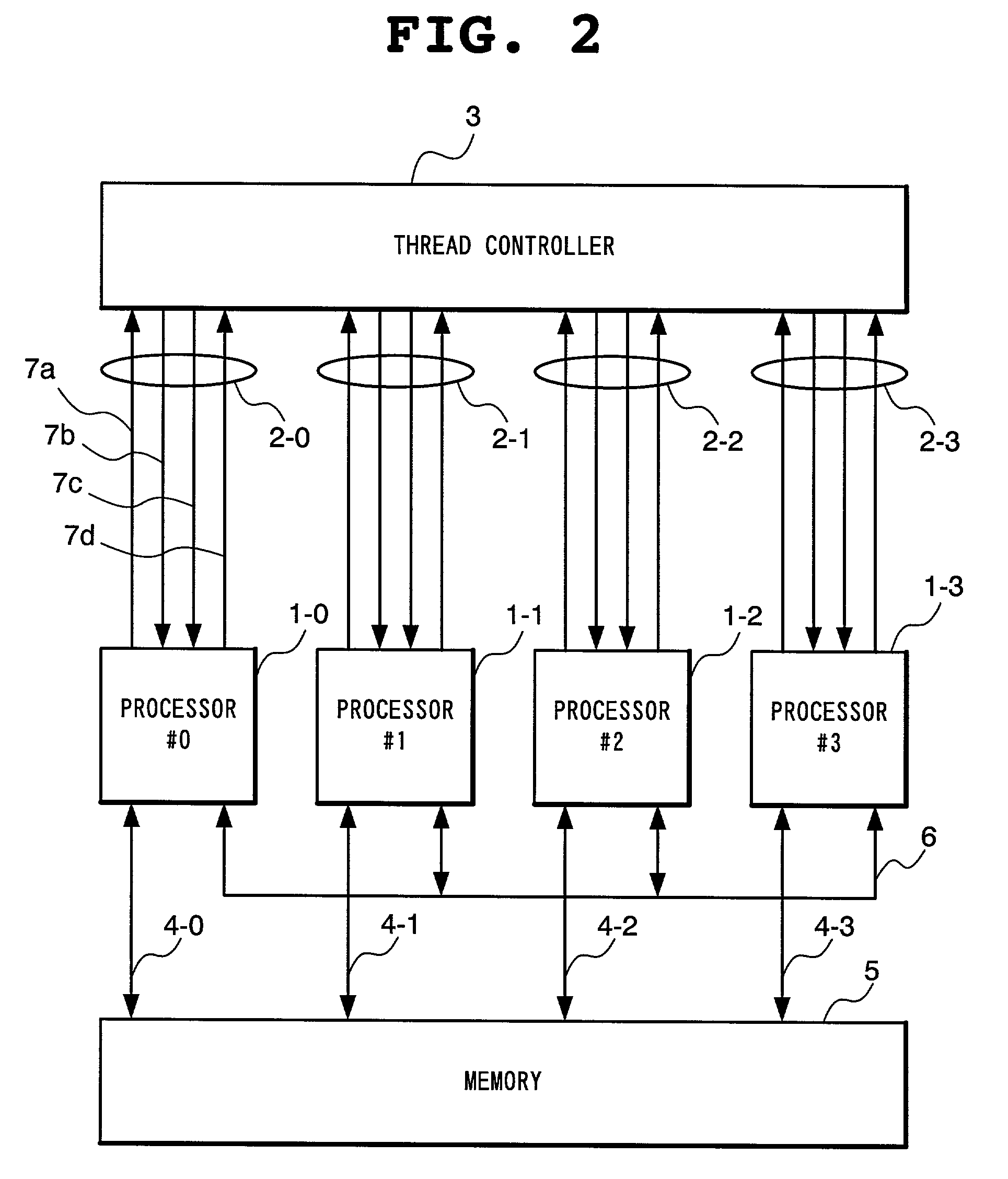
[0114]With reference to FIG. 2, one example of a parallel processor system of the present invention is a 4-thread parallel execution type processor in which four processors 1-i (i=0˜3) are connected to a thread controller 3 through a signal line 2-i and to a shared memory 5 as well through a signal line 4-i. In addition, the processors 1-i are connected to each other through a communication bus 6. Although the present embodiment is described taking a 4-thread parallel execution type processor as an example, the present invention is applicable in general to an n (≧2) thread parallel execution type processor such as an 8-thread or 16-thread parallel execution type processor. All the processors 1-i, the memory 5 and the thread controller 3 operate in synchronization with a clock. Preferably, all the processors 1-i are integrated on one semiconductor chip together with the memory 5 and the thread controller 3.
[0115]Each processor 1-i individually has a program counter (hereinafter refer...
second embodiment
[0137]The present embodiment differs from the first embodiment in that the need of a term instruction in a parallelization program is eliminated. In the following, the present embodiment will be described mainly with respect to the difference from the first embodiment.
[0138]With reference to FIG. 11, each processor 1-i of the parallel processor system according to the present embodiment includes, in addition to the components shown in FIG. 6, a register 28 for preserving a fork destination address accompanying the fork request 7a transmitted from the execution unit 23 to the thread controller 3, a coincidence circuit 29 for determining whether the value of the PC21 is coincident with a fork destination address preserved in the register 28 and an AND gate 30 for outputting a logical product of outputs of the forked bit 27 and the coincidence circuit 29 to the execution unit 23.
[0139]When the output of the AND gate 30 attains a logical “1” as a result of coincidence of the value of th...
third embodiment
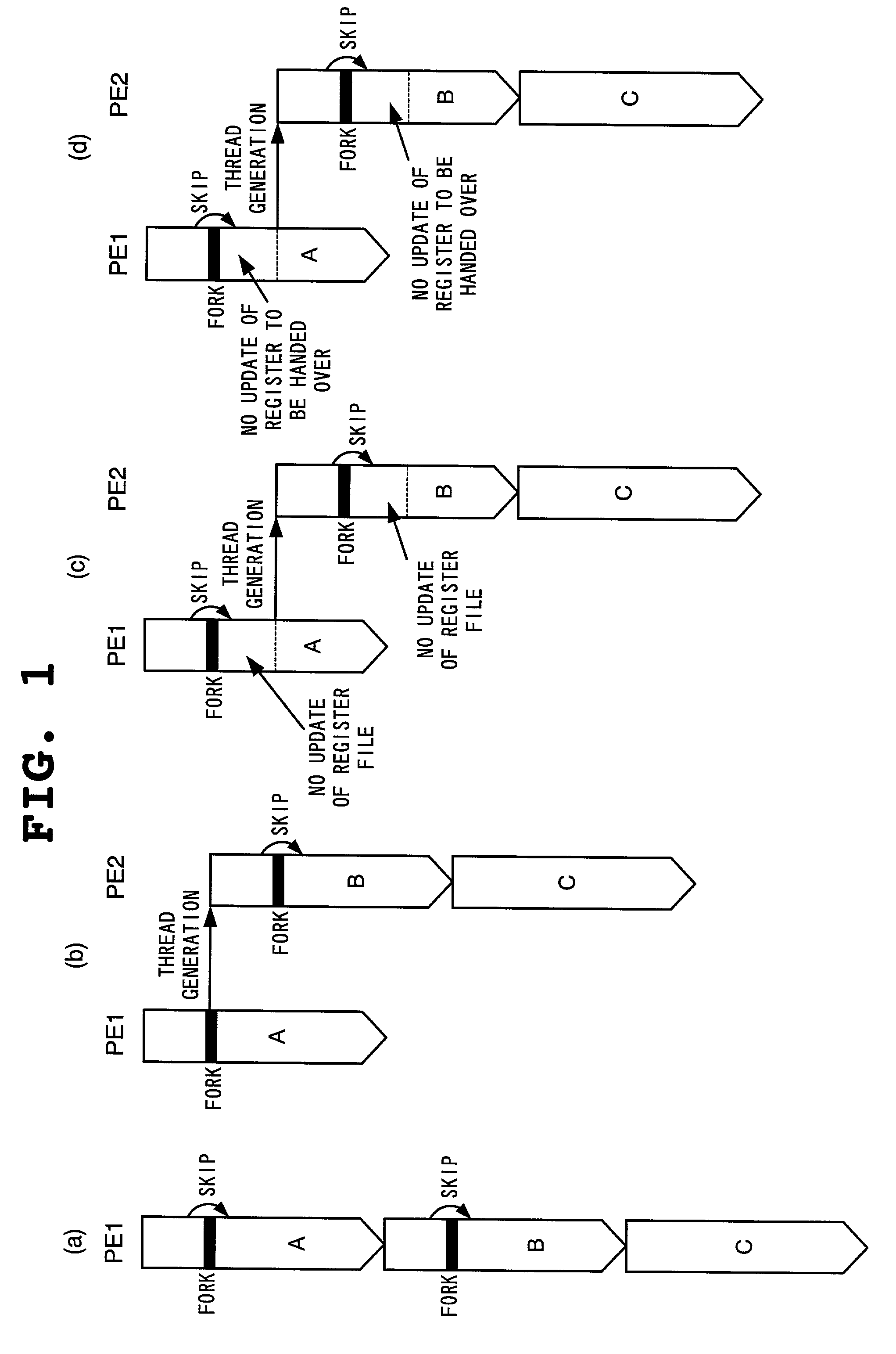
[0144]While in the first and second embodiments, forking is given up unless forking is possible at a fork point of a master thread, in the present embodiment, forking is conducted when there appears other processor which can start execution of a slave thread before a register file of a master thread is updated. In the following, the present embodiment will be described mainly with respect to the difference from the second embodiment.
[0145]With reference to FIG. 14, each processor 1-i of the parallel processor system according to the present embodiment includes, in addition to the components shown in FIG. 11, a fork valid bit 31. The fork valid bit 31 is set by a fork signal 37 output by the execution unit 23 when executing a fork instruction and reset by the fork response 7b received from the thread controller 3 and a register update signal 33 which the execution unit 23 outputs when updating any of the registers in the register file 25 of the master thread. The output of the fork v...
PUM
 Abstract
Description
Claims
Application Information
 - R&D
- Intellectual Property
- Life Sciences
- Materials
- Tech Scout
- Unparalleled Data Quality
- Higher Quality Content
- 60% Fewer Hallucinations
Browse by: Latest US Patents, China's latest patents, Technical Efficacy Thesaurus, Application Domain, Technology Topic, Popular Technical Reports.
© 2025 PatSnap. All rights reserved.Legal|Privacy policy|Modern Slavery Act Transparency Statement|Sitemap|About US| Contact US: help@patsnap.com


