Fluid measurements in a reaction vessel used in conjunction with a clinical analyzer

a reaction vessel and fluid measurement technology, applied in the field of analyte measurement, can solve the problems of increasing the potential of degrading throughput and overall system reliability, overall analytical error, and adding significant complexity and cost to the analyzer, so as to eliminate the large/small geometry effect of a reaction well, the effect of effective compensation or normalization

Inactive Publication Date: 2007-10-16
ORTHO-CLINICAL DIAGNOSTICS
View PDF15 Cites 11 Cited by
  • Summary
  • Abstract
  • Description
  • Claims
  • Application Information

AI Technical Summary

Benefits of technology

[0027]An advantage of the present invention is that reaction well geometry and other effects can be effectively compensated or normalized from a fluid volume measurement.
[0028]A further advantage of the presently described measurement method is that in addition to eliminating the large / small geometry effects of a reaction well, other interior well effects such as off-center probe positioning and well coating type and thickness errors, may also be minimized.

Problems solved by technology

Therefore and in certain prior art clinical analyzers, redundant detection schemes have been introduced for detecting incorrect volumes of fluid which are being delivered to a reaction well or vessel by the various fluidic metering subsystems of the analyzer.
In terms of attempting to remove well geometry as a significant contributor to the overall error budget, gravimetric measurements of reaction wells could be measured both prior to and after fluid delivery can remove reaction well geometry as a contributor to the overall analytical error which is described above.
However, this particular approach adds significant complexity and cost to the analyzer, as well as increasing the potential of degrading throughput and overall system reliability thereof.
This solution, however, would be extremely costly given that the manufacturing molds for reaction vessels are high yield, multi-cavity and have a material / wear issue based on the use of titanium dioxide which is abrasive and causes mold wear.
That is, mold maintenance and process control would increase while mold life would decrease, adding significant cost and complexity to the manufacturing of reaction wells.

Method used


Image

  • Fluid measurements in a reaction vessel used in conjunction with a clinical analyzer
  • Fluid measurements in a reaction vessel used in conjunction with a clinical analyzer
  • Fluid measurements in a reaction vessel used in conjunction with a clinical analyzer

Examples


Embodiment Construction

[0040]The following discussion relates specifically to the measurement of fluid volumes in reaction wells that are used in an exemplary clinical blood analyzer, namely, the ECi analyzer manufactured by the Johnson and Johnson Company. It will be readily apparent, however, that the approaches discussed herein are meant to be more generally applicable throughout the industry.

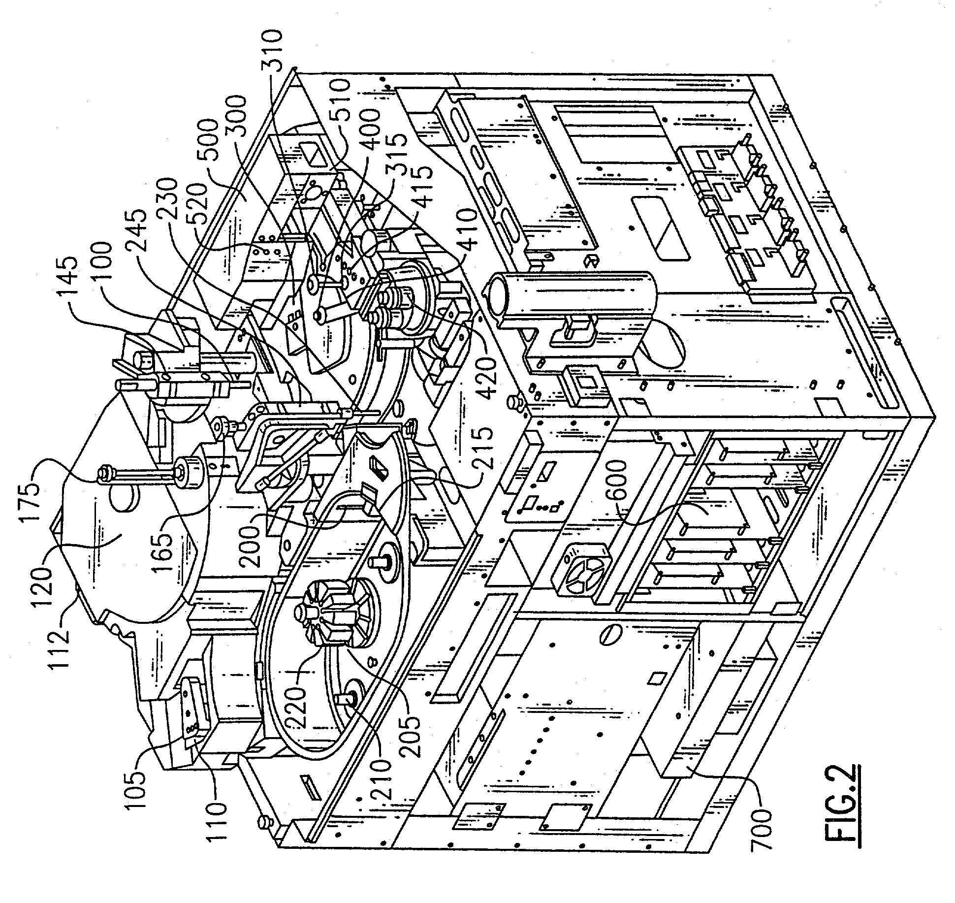
[0041]Referring to FIGS. 2 and 3, the basic operation of the above analyzer is first briefly discussed. The analyzer is designed to conduct automated enzyme immunoassays (EIAs) for analytes including hormones, vitamins, and related compounds, infectious disease markers, cancer markers, therapeutic drug monitoring, abused drug analysis, and other analytes amenable to analysis by EIA. To help further understand the present invention, the operation of the systems is broadly described with respect to the way an assay would be conducted on a sample.

[0042]The analyzer is categorized into systems of components and, where...


PUM

PropertyMeasurementUnit
volumeaaaaaaaaaa
volumeaaaaaaaaaa
volumeaaaaaaaaaa

Abstract

A method for measuring the amount of fluid contained in a reaction vessel in a clinical analyzer includes the steps of adding a first aliquot of fluid to the reaction vessel and measuring the quantity of fluid contained therein. A second aliquot of fluid is then added to the reaction vessel and the quantity of fluid contained therein is also measured. Measurement of the two fluid quantities can occur with or without removal of the first aliquot in between measurements. In obtaining the two quantity measurements and comparing them against a standard, the effects of well geometry can be minimized. Preferably, a delta or ratio measurement is obtained between the first and second liquid volume measurements which can be compared against a standard so as to normalize apparent volume losses or gains due to reaction well dimensional variation. This approach enhances the analytical capability to detect true fluid delivery errors.

Description

FIELD OF THE INVENTION[0001]The invention relates to the field of analyte measurement and in particular to a reliable method for determining fluid volumes in a reaction well wherein well geometry and other metering discrepancies can be accounted for in liquid volume determinations.BACKGROUND OF THE INVENTION[0002]Known clinical analyzers are employed for testing a large number of sample fluids for a particular analyte(s) of interest. In analyzers having so-called wet chemistry systems, sample fluid is typically placed in a sample reaction vessel, such as a cup or tube, in the analyzer so that aliquots can be dispensed or metered. Structurally within the analyzer, a probe or proboscis using appropriate fluidics such as pumps, valves, liquid transfer lines such as pipes or tubing, and driven by, pressure or vacuum are often used to meter and transfer a predetermined quantity of sample from the sample vessel to a reaction vessel. The sample probe or proboscis or a different probe or pr...

Claims


Application Information

Patent Timeline
Patent Type & Authority Patents(United States)
IPC IPC(8): G01N1/10G01F23/00G01F23/26
CPCG01F23/26Y10T436/12Y10T436/11Y10T436/10Y10T436/2575Y10T436/115831
Inventor VANBRUNT, NICHOLASBOWER, RANDY K.BURKOVICH, ROBERT A.DAMBRA, JOSEPH J.
Owner ORTHO-CLINICAL DIAGNOSTICS
Why Eureka
Try Eureka