
Method and equipment for feeding two gases into and out of a multi-channel monolithic structure

Inactive Publication Date: 2007-10-23
STATOIL ASA PETRO SA (NO)
View PDF25 Cites 63 Cited by
  • Summary
  • Abstract
  • Description
  • Claims
  • Application Information

AI Technical Summary

Benefits of technology

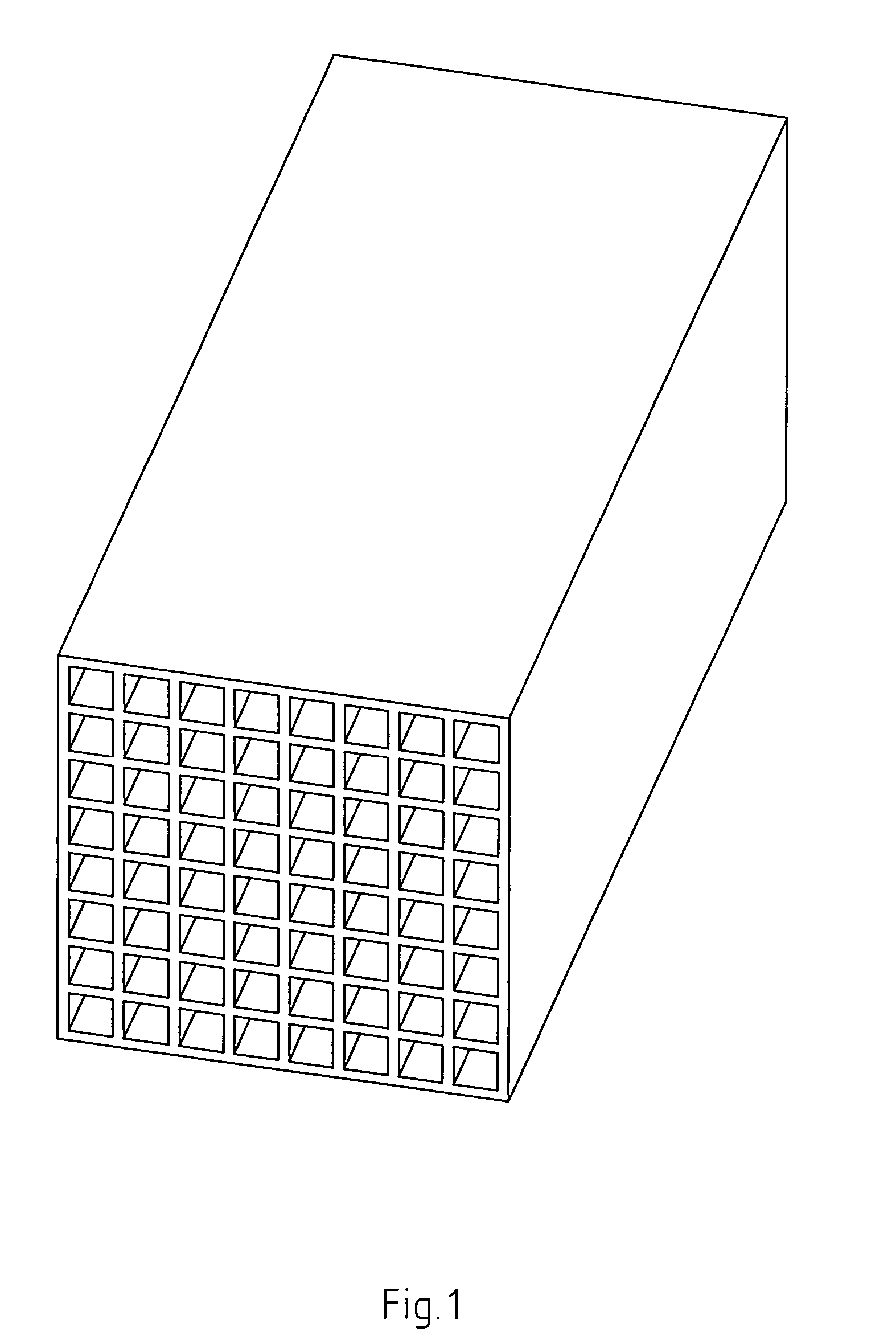
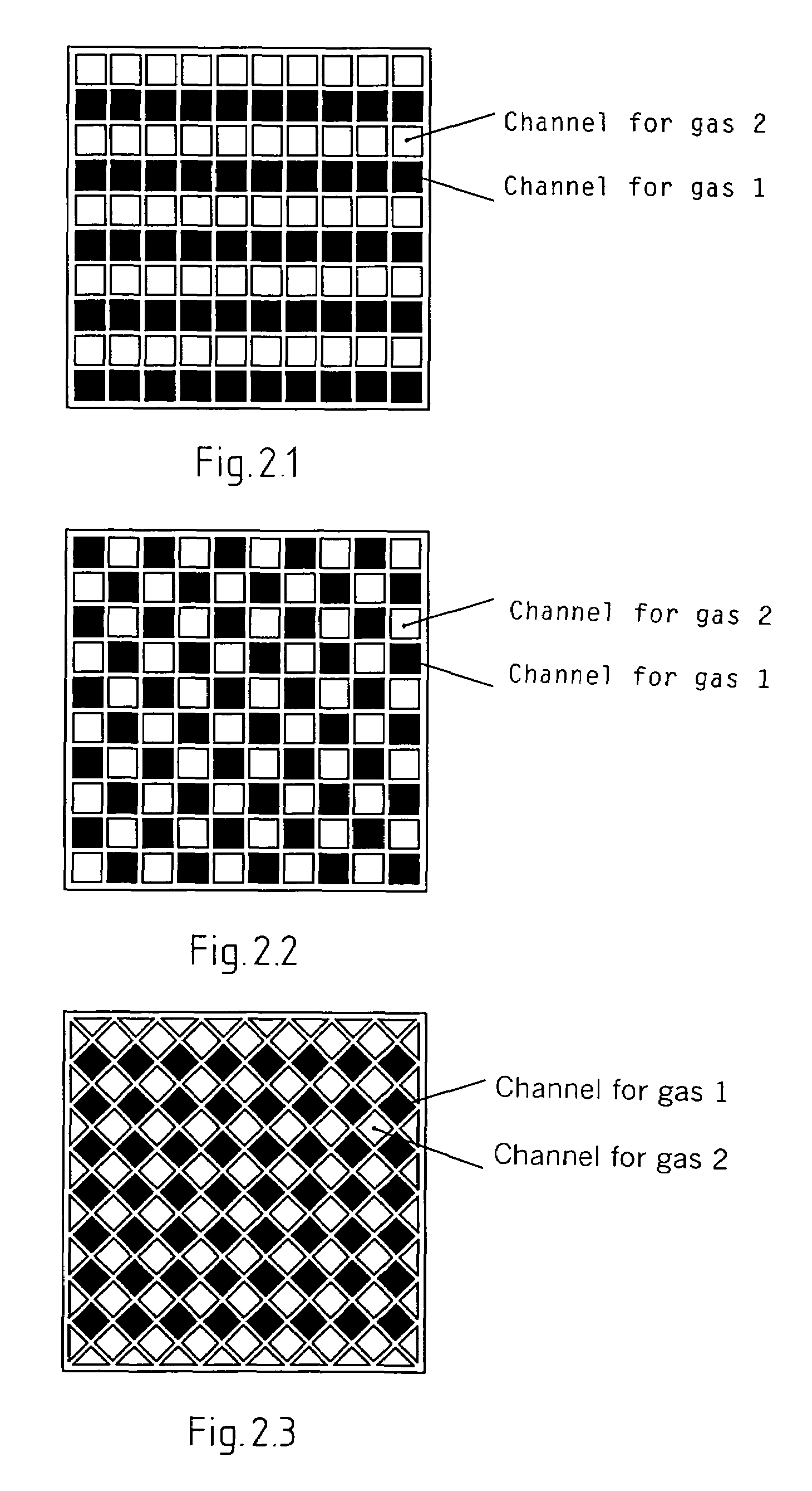
[0014]By using extrusion technology for production of a monolithic structure, there is great opportunity to influence the geometric shape of the channels. Extrusion as a production method means that the entire monolithic structure is made in one operation. The channels' cross-sectional area may differ in both shape and size. The channels' cross-sectional area can be made uniform in size and shape, which is most common, for example triangular, square or hexagonal. However, combinations of several geometric shapes are also conceivable. The geometric shape, together with the size of the channel, will be significant for the mechanical strength and available surface area per volume unit.

Problems solved by technology

Such regenerative heat exchange processes with cycles in which there is alternation between two gases (one hot, one cold) in the same structure is not, however, suitable where mixture of the two gases is undesirable or where stable and continuous heat and / or mass exchange is desired.
The industrial use of monoliths is limited mainly to applications in which only one gas flows through all the channels at the same time.
Although it has been shown that it will be advantageous to use monoliths for mass and / or heat exchange between two gases in a number of applications, industrial use of monoliths for such applications is not very widespread.
One of the most important points of complaint or reasons why monoliths are not used in this area is that the prior art technology for feeding the two gases into and out of the monolith's separate channels is complicated and not very suitable for scaling up (i.e. interconnection of several monolith units), particularly when the large number of channels in a monolith are taken into consideration.
This increases the likelihood of crack formation and undesired leakage with mixture of the two gases as a consequence.
A cooling system will naturally make the monolithic structure more expensive and more complicated, particularly for applications on a large scale in which the monolith consists of many thousand channels and in which it is also necessary to use many monolithic structures in series and / or in parallel to achieve a sufficient surface area.
The biggest disadvantage of this method, apart from the necessary processing (cutting and sealing) of the monolithic structure itself, is that only half of the available area for mass and / or heat exchange can be utilized.

Method used


Image

  • Method and equipment for feeding two gases into and out of a multi-channel monolithic structure
  • Method and equipment for feeding two gases into and out of a multi-channel monolithic structure
  • Method and equipment for feeding two gases into and out of a multi-channel monolithic structure

Examples


example 1

[0099]Table 1 shows two alternatives that are calculated to show the effect of radiation when a wall internally between two colder gas channels is radiated by a hotter wall. T3 and T4 indicate the mean gas temperature for cold gas and hot gas respectively.

[0100]

TABLE 1Numerical values used to calculate the effect of radiation from a hot wallto a wall between two gas channels with colder gas.HotHot gasColdColdHot gasCold gasAlt.gas inoutgas ingas outmean (T4)mean (T3)1(° C.)1 2561 0501 0191 2211 1531 1201(° K.)1 4261 3932(° C.)1 093 505 4531 000 799 7272(° K.)1 0721 000

[0101]A wall temperature T1 is assumed midway between the hot and cold gas temperatures, and the following is produced:

[0102]

Alt 1Alt 2T1 (° K.)1 4101 036(Temperature of wall between hot and cold gas)T2 (° K.)1 3931 000(Temperature of cold gas)λ = 0.1 W / mK(Thermal capacity of gas)b = 2.0 mm(Distance between walls)εo = 5.67 10−8 W / m2K(Stefan Bolzmann's constant)εr = 0.9(Emissivity of walls)P1 = λ / b * 3.75 * (T1 − T3) = ...


PUM


Abstract

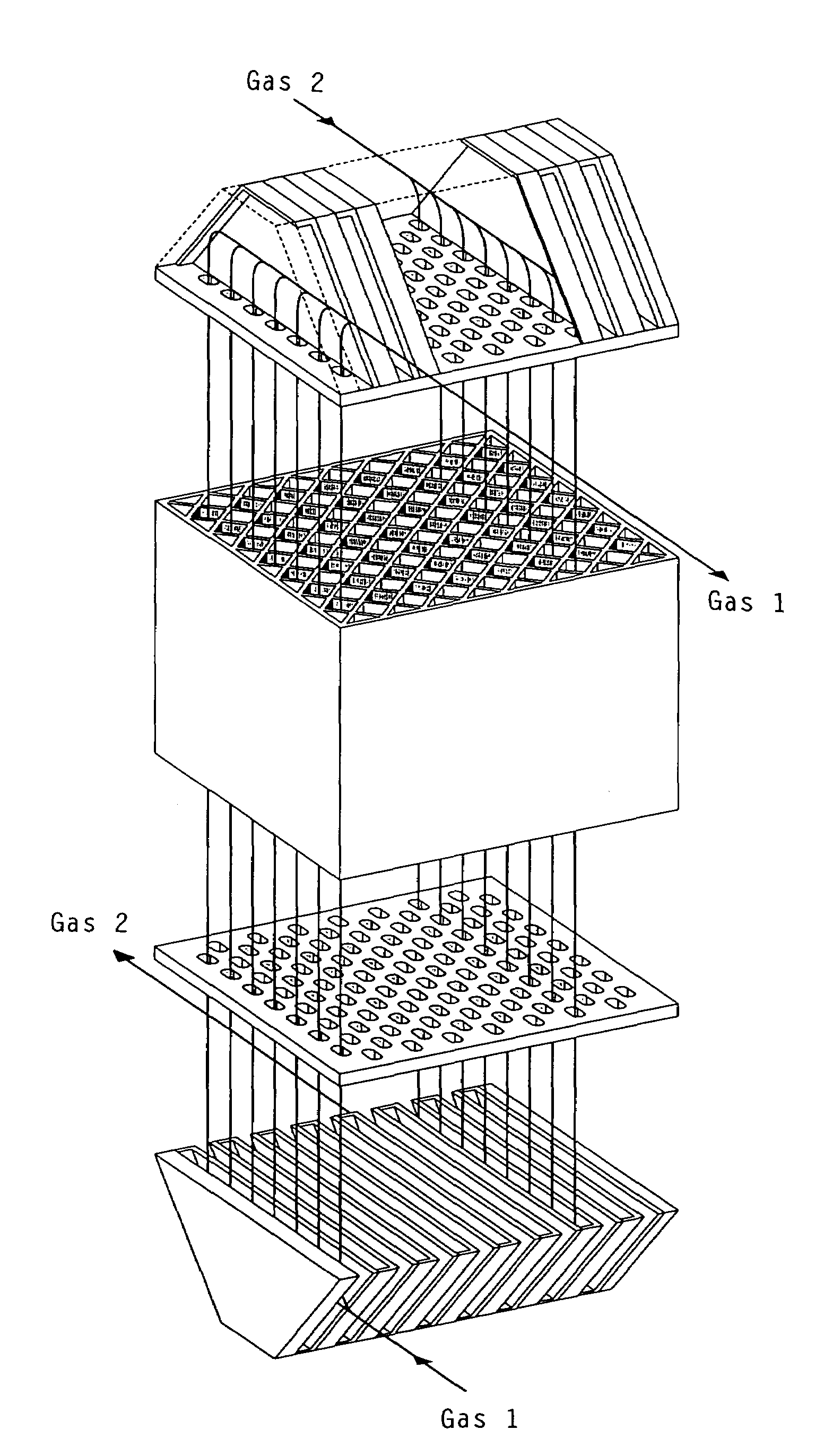
A method with associated equipment for feeding two gases into and out of a multi-channel monolithic structure. The two gases will normally be gases with different chemical and / or physical properties. The first gas and the second gas are fed by means of a manifold head into channels for the first and second gases, respectively. The gases are distributed in the monolith in such a way that at least one of the channel walls is a shared or joint wall for both gases. The walls that are joint walls for the two gases will then constitute a contact area between the two gases that is available for mass and / or heat exchange. This means that the gases must be fed into channels that are spread over the entire cross-sectional area of the monolith. The entire contact area or all of the monolith's channel walls are directly used for heat and / or mass transfer between the gases. This means that the channel for one gas will always have the other gas on the other side of its channel walls.

Description

BACKGROUND OF THE INVENTION[0001]1. Field of the Invention[0002]The present invention concerns a method with associated equipment for feeding two gases into and out of a multi-channel monolithic structure. The two gases will normally be two gases with different chemical and / or physical properties.[0003]2. Description of Related Art[0004]The gases, here called gas 1 and gas 2, are fed into channels for gas 1 and channels for gas 2 respectively. Gas 1 and gas 2 are distributed in the monolith in such a way that at least one of the channel walls is a shared or joint wall for gas 1 and gas 2. The walls that are joint walls for the two gases will then constitute a contact area between the two gases that is available for mass and / or heat exchange. This means that the gases must be fed into channels that are spread over the entire cross-sectional area of the monolith. The present invention makes it possible to utilize the entire contact area or all of the monolith's channel walls directly ...

Claims


Application Information

Patent Timeline
IPC IPC(8): F28F9/02F28F21/04F28D7/00F23C13/00F28D9/00F28F7/02F28F27/02
CPCF23C13/00F28F7/02F28F9/0278F23C2900/03001Y10S165/395F23C2900/13001
Inventor BRUUN, TORWERSWICK, BJORNARKRISTIANSEN, KAREGRONSTAD, LEIF
Owner STATOIL ASA PETRO SA (NO)
Learn More