
Combined casing expansion/casing while drilling method and apparatus

a casing and drilling method technology, applied in the direction of drilling pipes, rotary drilling, borehole/well accessories, etc., can solve the problems of time-consuming and costly process, and the possibility of reinserting the drilling apparatus, so as to reduce the time spent expanding the casing and increase the drilling speed , the effect of reducing the drilling cos

Active Publication Date: 2007-10-30
HALLIBURTON ENERGY SERVICES INC
View PDF12 Cites 23 Cited by
  • Summary
  • Abstract
  • Description
  • Claims
  • Application Information

AI Technical Summary

Benefits of technology

[0021]The present invention offers increased drilling speed by reducing the time spent expanding the casing and eliminating the need to withdraw the drill string from the wellbore to insert casing. Reduced drilling costs also result due to a reduction in drilling time and elimination of steps and equipment used in the conventional drilling process.

Problems solved by technology

The process is time consuming and costly.
If the depth of the wellbore is ever later to be extended, it is not possible to reinsert the drilling apparatus into the cased wellbore without resorting to a smaller diameter casing string.

Method used


Image

  • Combined casing expansion/casing while drilling method and apparatus
  • Combined casing expansion/casing while drilling method and apparatus
  • Combined casing expansion/casing while drilling method and apparatus

Examples


Embodiment Construction

[0027]In the following description, in referring to the position of components in the drill strings, “above”, “up”, “upper” and the like describe relative positions closer to the ground surface while “below”, “down”, “lower” and the like describe relative positions closer to the bottom of the wellbore.

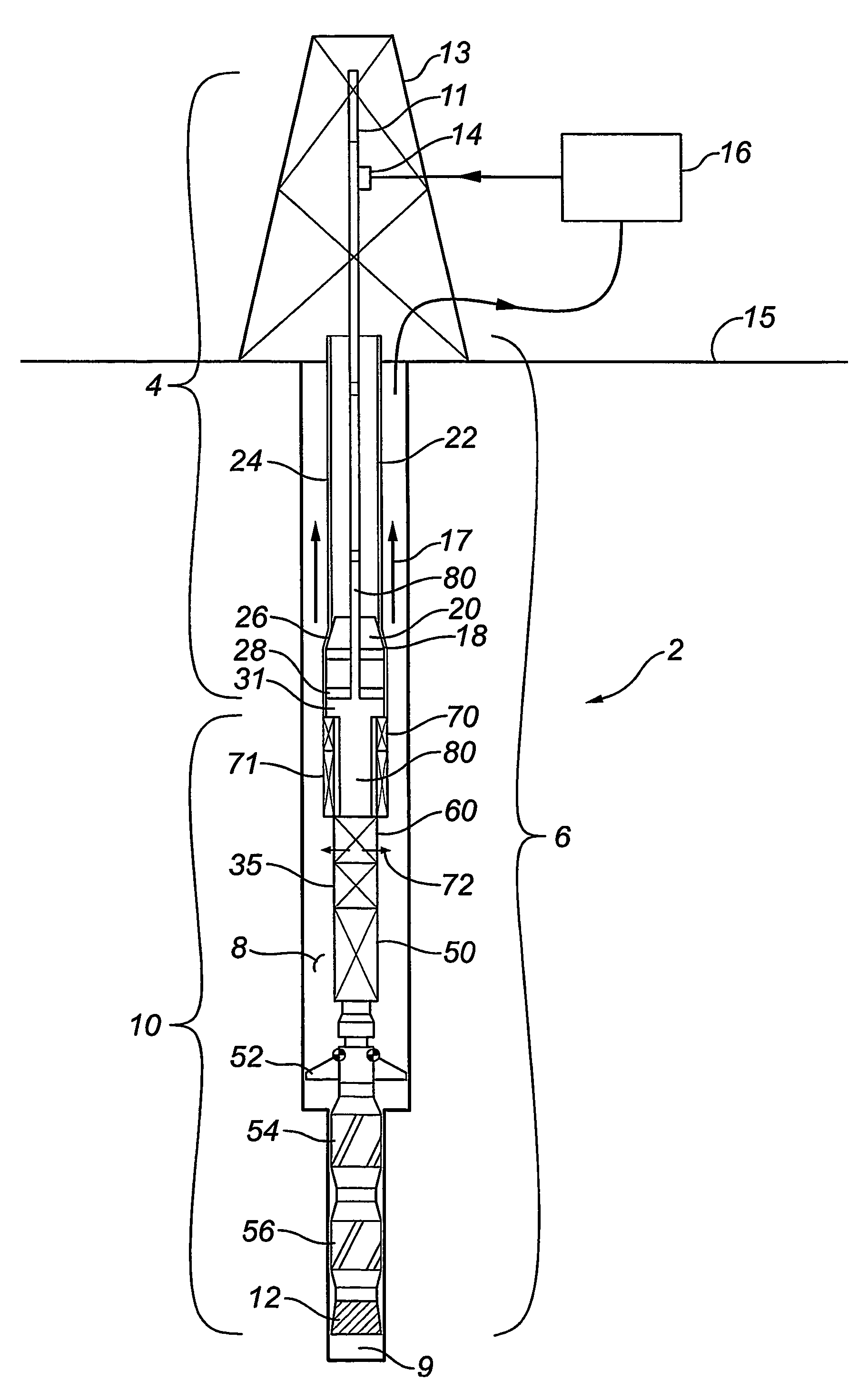
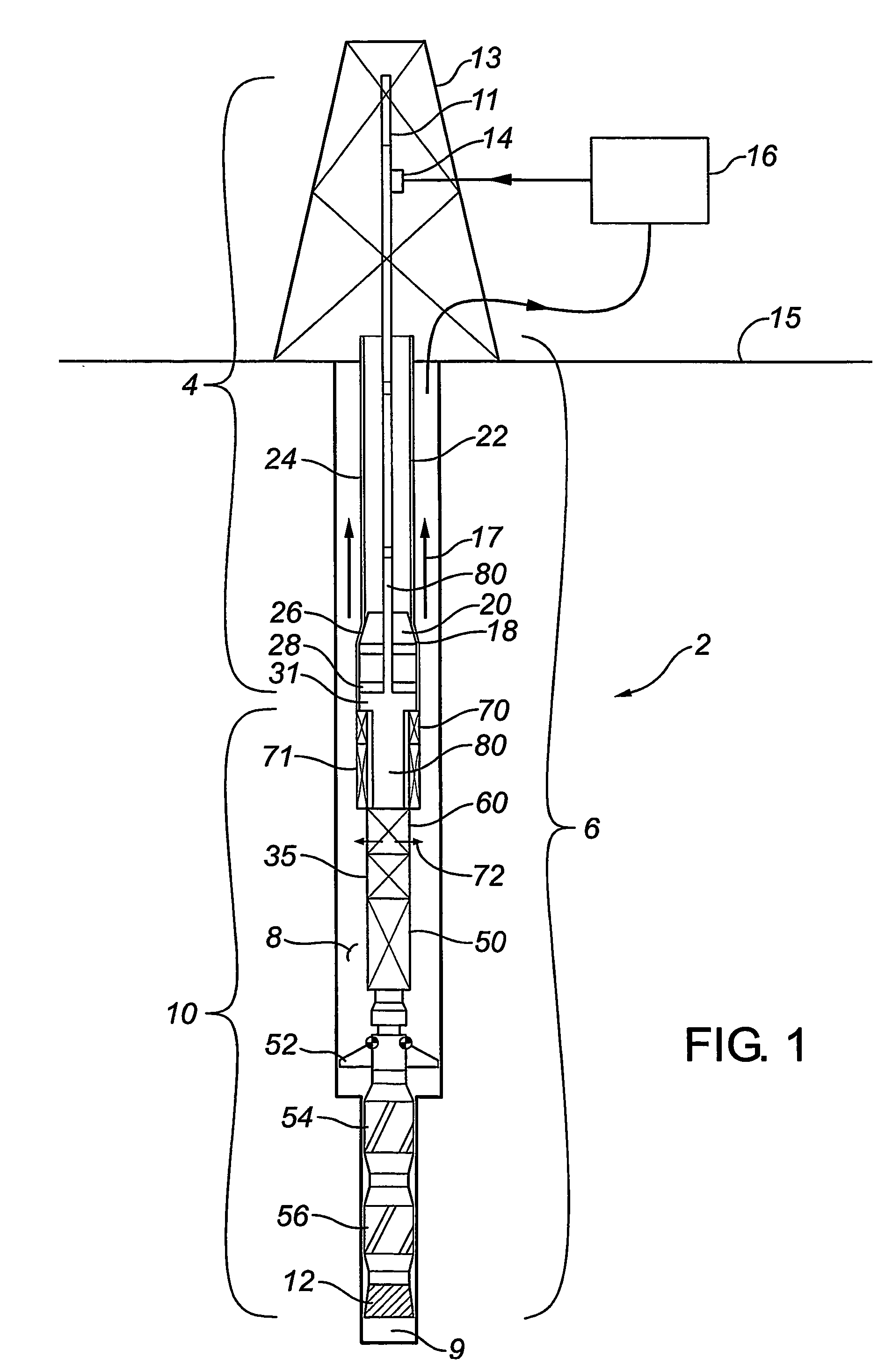
[0028]Referring to FIG. 1, there is shown in schematic form an embodiment of a drilling system according to the present invention intended for sliding drilling. The drilling assembly 2 comprises an upper drill string 4 and a lower drill string 6 adapted for insertion into a wellbore 8 created by the drilling assembly. The lower end 9 of lower drill string 6 includes a bottom hole assembly (BHA) 10 which includes a drill bit 12, for example, a roller cone bit. A fluid passage 80 extends through upper drill string 4 and lower drill string 6 for distributing drilling fluid, also, for example, known as drilling “mud”, to bottom hole assembly 10 to permit operation of drill bit 12. Upper dr...


PUM


Abstract

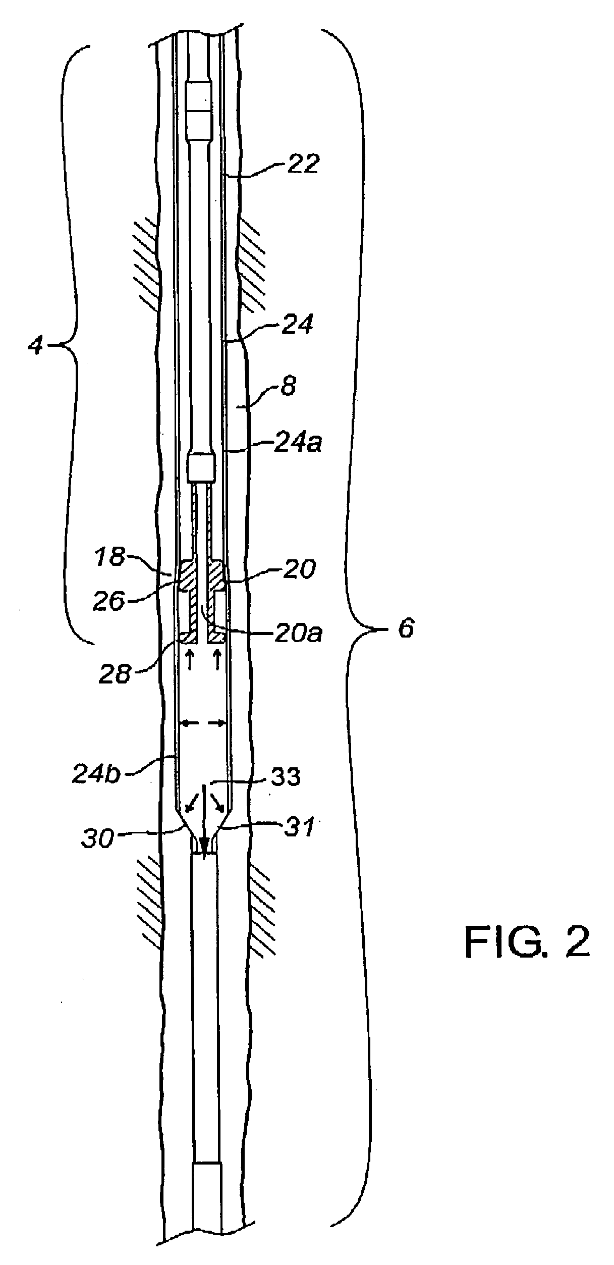
A drilling assembly (2) comprises upper (4) and lower (6) drill strings with a fluid passage (80) therethrough for distributing fluid to a bottom hole assembly (10). The upper drill string (4) has an upper end (11) connectable to a drilling apparatus (13) and fluid source (16) and a lower end (18) with an attached casing expander unit (20) that communicates the fluid passage (80) of the upper (4) and lower (6) drill strings. An upper end (22) of the lower drill string (6) is formed from a casing string (24) telescoped over the casing expander unit. A constriction (31) connects the casing string (24) with the rest of the lower drill string (6). A flow restriction device (35) in the lower drill string acts to control fluid flow through the fluid passage. In use, the flow restriction device creates a pressure in the fluid passage that acts at the constriction to advance the lower drill string past the upper drill string while simultaneously expanding the portion of the casing string moving past the expander unit.

Description

FIELD OF THE INVENTION[0001]This invention relates to drilling tools and methods and is specifically concerned with a casing drilling system in which a casing string is run into the wellbore with the drilling string and expanded while the drilling string is in the wellbore.BACKGROUND OF THE INVENTION[0002]The drilling of wells for oil and gas production conventionally employs relatively small diameter drilling pipe joined end to end to form a drill string to which is secured the necessary equipment including a drill bit for creating a wellbore which is of larger diameter than the drilling pipe. After a portion of the wellbore has been drilled, the wellbore is usually lined with a string of tubular casing member joined end to end to define a casing string. This conventional approach requires a cycle of drilling the wellbore, pulling the drill string out of the wellbore to the surface and running casing into the wellbore. The process is time consuming and costly.[0003]The technique of...

Claims


Application Information

Patent Timeline
Patent Type & Authority Patents(United States)
IPC IPC(8): E21B7/20E21B43/10
CPCE21B43/103E21B7/20
Inventor HAY, RICHARD T.KENT, GERALD EDWARDKEEN, JR., JERRY LAVELLEREID, CHARLES M.
Owner HALLIBURTON ENERGY SERVICES INC
Learn More