Radar apparatus

a technology of radar and antenna, applied in diversity/multi-antenna systems, instruments, reradiation, etc., can solve the problems of limited mounting space and limited position of radar apparatus so as to transmit radio waves forward, and achieve the effects of enhancing the performance of radar apparatus, reducing the size and cost of radar apparatus, and increasing the number of channels

Inactive Publication Date: 2007-10-30
FUJITSU GENERAL LTD
View PDF23 Cites 72 Cited by
  • Summary
  • Abstract
  • Description
  • Claims
  • Application Information

AI Technical Summary

Benefits of technology

[0018]On the other hand, when such a radar apparatus is mounted as an electronic apparatus, for example, on an automobile or the like, the position where it can be mounted so as to transmit the radio wave forward is limited, and the available mounting space is quite restricted. The radar apparatus used in such an environment must be made as small as possible. Accordingly, while the number of antennas can be reduced, the above radar apparatus still leaves much to be desired when it comes to size reduction. Furthermore, from the standpoint of vehicle driving safety, it is desired to further increase the performance of the radar apparatus for recognizing targets ahead of the vehicle, and it is also desired to reduce the cost of the apparatus.
[0034]The radar apparatus configuration described above makes the fabrication of the radar apparatus easier and achieves a reduction in cost and, when applying the radar apparatus, for example, as an anti-collision radar apparatus to be mounted on a vehicle or the like, the overall shape of the radar apparatus can be made suitable for mounting on the vehicle, and the processing for azimuth detection can be made faster and efficient, offering advantages in collision avoidance applications.

Problems solved by technology

On the other hand, when such a radar apparatus is mounted as an electronic apparatus, for example, on an automobile or the like, the position where it can be mounted so as to transmit the radio wave forward is limited, and the available mounting space is quite restricted.

Method used


Image

  • Radar apparatus
  • Radar apparatus
  • Radar apparatus

Examples


first embodiment

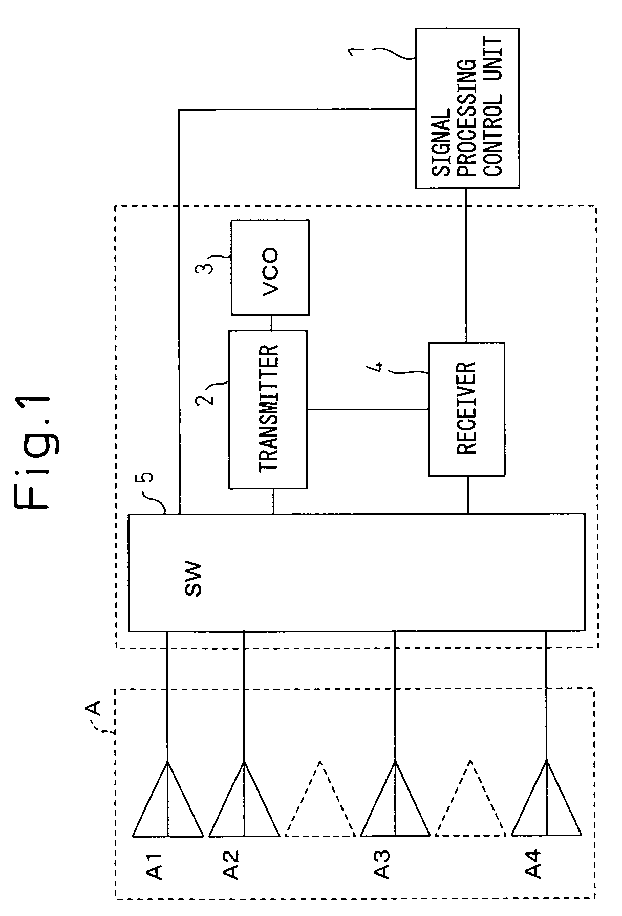
[0096]In view of this, the receiving signal channel switching sequence relating to antenna transmission and reception in the radar apparatus shown in FIG. 1 is modified so that the multi-channel formation can be switched between a coarse mode and a fine mode depending on the environment in which the radar is used for operation, and so that the mode can be switched from the fine mode to the coarse mode when a faster azimuth detection speed is needed. FIGS. 8 and 9 show the antenna switching operation in the radar apparatus of the present invention.

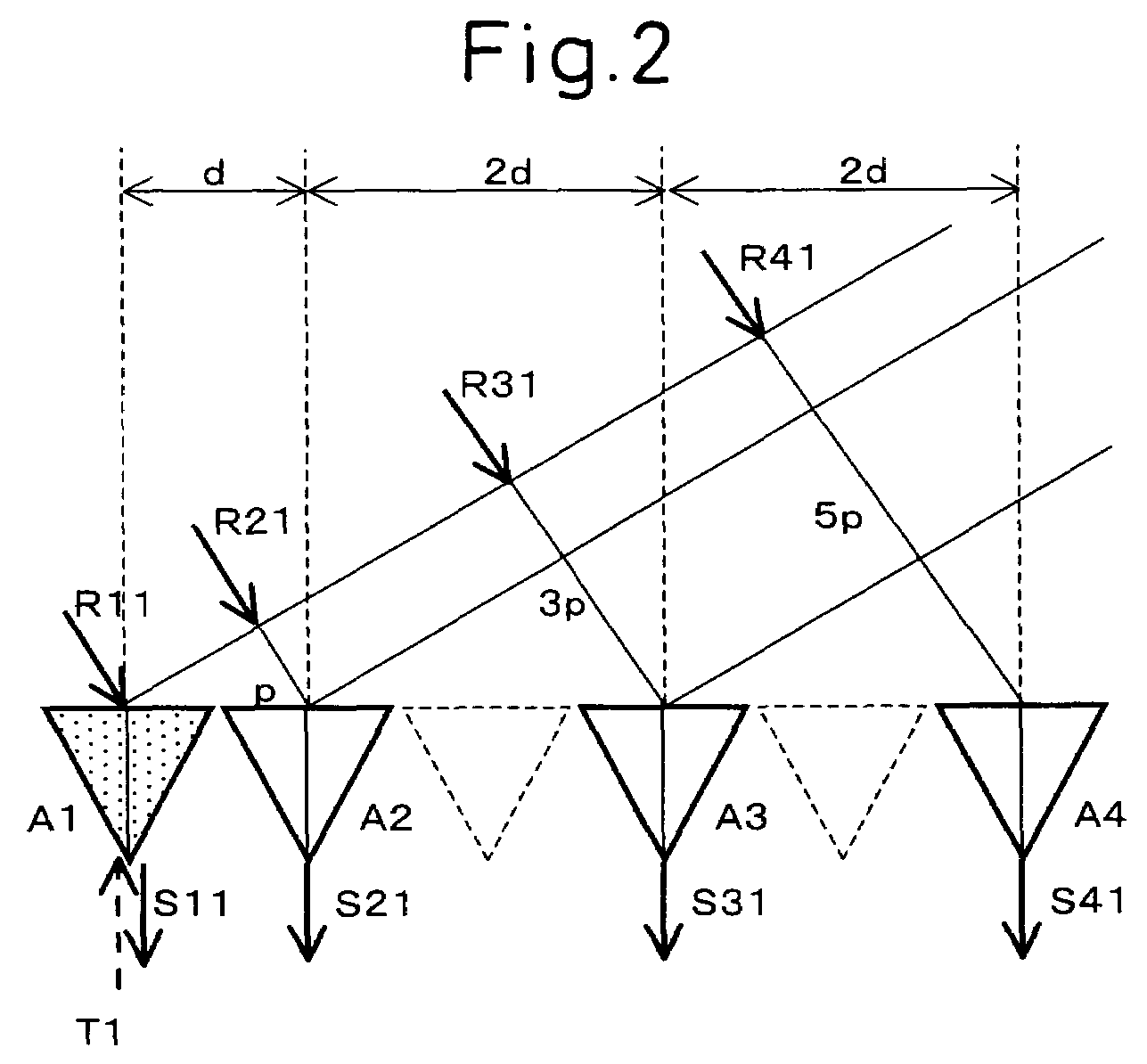
[0097]First, suppose that a radio wave is transmitted as a transmitted signal T1 from the first selected antenna A1, as shown in FIG. 2. The shaded triangle in the figure indicates the transmitting antenna selected for transmitting the radio wave. The radio wave transmitted from the transmitting antenna A1 is reflected by a target object, and its reflected wave returns to the antenna array A. The radio wave arriving from the direction of an...

second embodiment

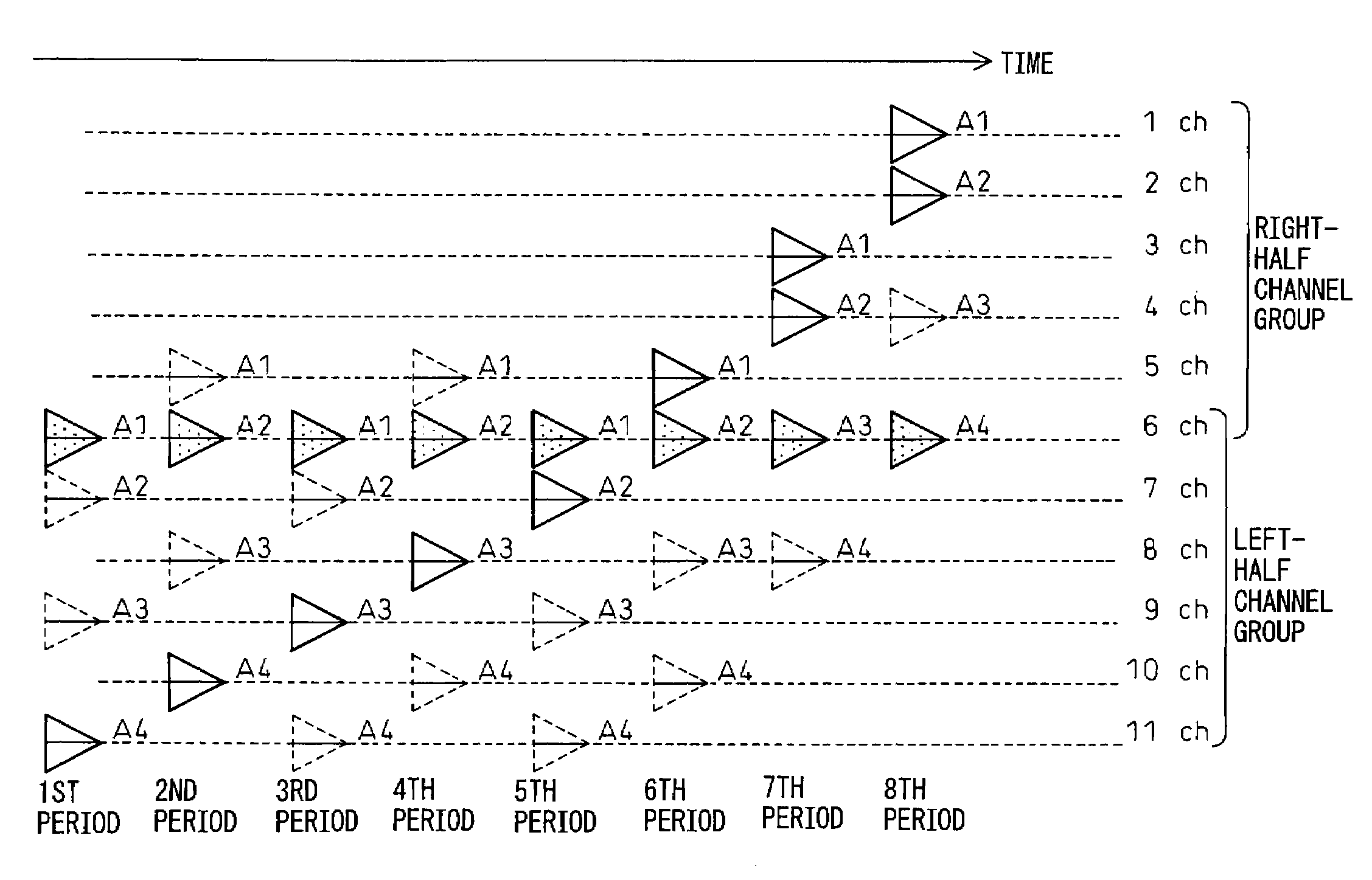
[0109]FIGS. 10 and 11 show a second embodiment in which the receiving signal channel switching sequence relating to antenna transmission and reception in the radar apparatus shown in FIG. 1 is modified so as to enhance the accuracy of azimuth detection; in this embodiment, the multiple receiving signal channels to be formed for the detection of a target object located ahead of the radar apparatus are divided into two groups, the left group and the right group, and multiple beams are formed using the plurality of channels in the left half and the plurality of channels in the right half, respectively, so that the processing for azimuth detection can be performed twice.

[0110]In FIG. 10, as in FIG. 4, the timing for switching between the transmitting antennas A1 to A4 and the receiving antennas A1 to A4 is shown in time series in conjunction with the triangular wave cycles of the transmitted FM-CW wave. In FIG. 10 also, receiving antenna 1 indicates each of the transmitting antennas A1 ...


PUM


Abstract

The present invention relates to a radar apparatus that forms multiple digital beams based on reflected waves of a transmitted radio wave. A transmit signal is transmitted in a predetermined cycle from one of transmitting / receiving antennas A1 to A4 arrayed in a row. The antennas A1 to A4, each switched between transmission and reception, are arranged such that the ratio of the spacing between one pair of adjacent antennas to the spacing between the other pair of adjacent antennas is 1:2. The reflected waves are received by the respective antennas, and DBF is performed based on the resulting received signals. Eleven-channel DBF is achieved using the four antennas with a space equivalent to six antennas. By achieving multiple channels with a minimum number of antennas, the size and cost of the apparatus can be reduced while also reducing the processing time and thus enhancing the performance.

Description

CROSS-REFERENCE TO RELATED APPLICATION[0001]This application claims the priority of Japanese Patent Application Number 2004-182537, filed on Jun. 21, 2004.BACKGROUND OF THE INVENTION[0002]1. Field of the Invention[0003]The present invention relates to a radar apparatus that uses a frequency-modulated continuous wave (FW-CW) as a transmit wave and, more particularly, to a radar apparatus that performs scanning for receiving reflected waves of a transmitted radiowave by digital beam forming (DBF).[0004]2. Description of the Related Art[0005]Various radar apparatuses, of a type that performs scanning on receive by using DBF, have been developed and are known in the prior art. Generally, the basic configuration of this type of radar apparatus employs a single transmitting antenna and a plurality of receiving antennas, and a radiowave is transmitted from the transmitting antenna and reflected waves of the transmitted radiowave are received by the plurality of antennas.[0006]The present i...

Claims


Application Information

Patent Timeline
Patent Type & Authority Patents(United States)
IPC IPC(8): G01S13/00G01S13/93G01S7/03G01S13/32G01S13/34H01Q3/24H01Q3/26H04B7/06H04B7/08
CPCG01S7/034H04B7/0814H01Q3/26H04B7/0606H01Q3/24G01S13/345
Inventor SHIMA, NOBUKAZU
Owner FUJITSU GENERAL LTD
Why Eureka
Try Eureka