
Optical fiber ribbon with improved stripability

a technology of optical fiber and stripability, applied in the field of optical fiber and optical fiber ribbons, can solve the problems of poor peeling performance of the ribbon, difficulty in obtaining a fast cure speed, and increased surface friction

Active Publication Date: 2007-10-30
CORNING INC
View PDF23 Cites 17 Cited by
  • Summary
  • Abstract
  • Description
  • Claims
  • Application Information

AI Technical Summary

Benefits of technology

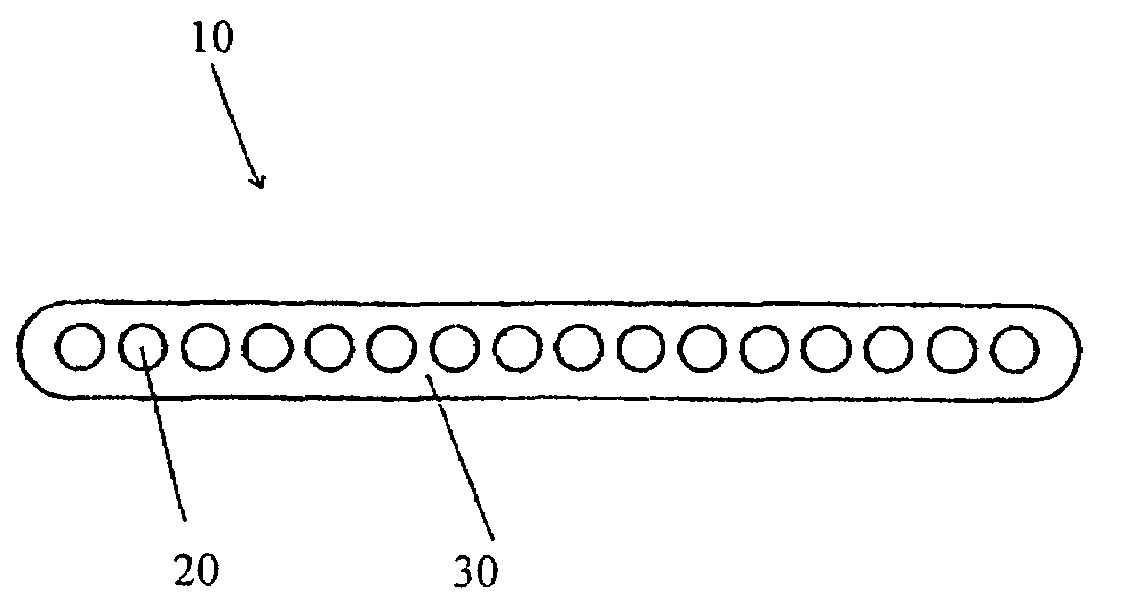
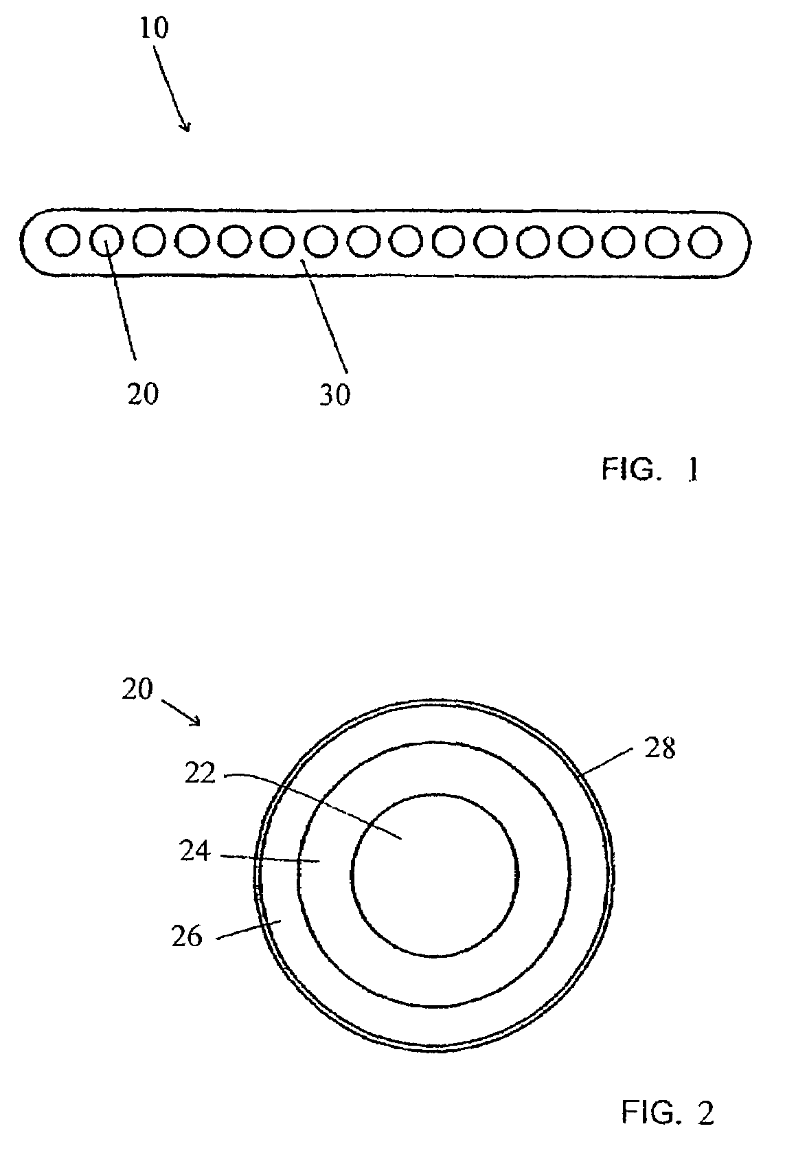
The present invention relates to an optical fiber ribbon that includes a plurality of optical fibers encapsulated within a matrix material. The coating, matrix, and ink layer (if present) are characterized by compatible chemical and physical properties, which allows for reliable stripping of the fiber coating and matrix from the optical fibers during installation. The invention also includes an ink formulation that has a high cure speed and is compatible with the matrix material. The method of making the optical fiber ribbon involves providing optical fibers with a coating, optionally applying an ink composition, and encapsulating the fibers in a matrix composition. The use of such ribbons results in significant savings during installation of optical fiber ribbons in telecommunication transmission systems.

Problems solved by technology

The pigments also absorb light so obtaining a fast cure speed is a challenge.
If the ink is under-cured this can cause problems including, but not limited to, increased surface friction, poor ribbon peel performance (where the matrix material forms a very high bond with the ink due to residual acrylate groups on the ink surface), and the propensity for the ink layer to come off of the fiber during ribbon handling or stripping.
For example, if the lamp intensity becomes low or the quartz tube in the lamp assembly becomes dirty, less UV light will be available to cure the inks and the result will be a low degree of cure on the inked fiber.
Inks with low cure speeds are also disadvantaged from the standpoint that inking line speeds cannot be increased to facilitate higher output.
With an undesirable amount of debris, it is necessary to remove the debris, for example, by wiping the stripped fibers with an alcohol-moistened cloth.
Unfortunately, with more debris, it is often necessary to wipe the fibers more than once.
Correcting the problem of excessive debris therefore requires additional labor, time, and cost.
Additionally, the act of repeated wiping may have the undesired consequence of weakening the glass fiber within the splice junction.

Method used


Image

  • Optical fiber ribbon with improved stripability
  • Optical fiber ribbon with improved stripability
  • Optical fiber ribbon with improved stripability

Examples


example 1

Preparation of Optical Fiber Ribbons

[0084]Optical fiber ribbons were fabricated using previously prepared optical fibers that possessed either a high Tg (>60C) secondary coating (“Coating A”) or a lower Tg (<55C) secondary coating (“Coating B”). The compositions are detailed below in weight percent in Table 1, except that those ingredients listed in pph were added to the 100 percent weight of the coating.

[0085]

TABLE 1Coating CompositionsComponentCoating ACoating BPhotomer 3016 (Cognis) 20%  5%Photomer 4028 (Cognis) 77% 82%KWS4131 (Bomar)  0% 10%Lucirin TPO (BASF)1.5%1.5%Irgacure 184 (Ciba)1.5%1.5%Irganox 1035 (Ciba)0.5 pph0.5 pph

[0086]Ink compositions that were used to cover the optical fibers included either DSM-751 (“Ink A”), an ink coating commercially available from DSM Desotech, Inc. (Elgin, Ill.); Coating A, a clear ink base with no added pigment dispersions (“Ink B”), and Coating B, a clear ink base with no added pigments (“Ink C”).

[0087]While “Ink B” and “Ink C” were tested ...

example 2

Testing of Ribbons for Strip Cleanliness

[0092]All ribbons were stripped using a Sumitomo JR4A stripper set at 90° C. Stripping was performed by hand, at either subjectively defined slow or fast rates. Ribbon strip performance was evaluated with ratings assigned for both cleanliness and tube-off.

[0093]Strip cleanliness was measured by examining the stripped optical fiber for debris. As described above, a score of one (1) identifies a fiber having a low amount of debris on its surface and a score of five (5) represents a fiber having a significant amount of debris on its surface. Any score of three (3) or less was deemed to be acceptable strip cleanliness. Cleanliness measurements were obtained by visually inspecting a segment of the stripped ribbon fibers with the naked eye. Particles remaining on the stripped ribbon fibers were examined and compared to limit samples which were rated according to the following standard:

[0094]

Number of ParticlesCleanliness Rating 0–10111–20221–403>40 ...

example 3

Comparison of Marking Ink Degree of Cure and Marking Ink Cure Speed.

Ink formulations were prepared according to the compositions listed below in Table 5

[0097]

TABLE 5Inventive Ink Compositions - Fast Cure SpeedComponentVioletRedWhiteBlueBrownBlackYellowPhotomer20% 20% 20% 20% 20% 20% 20% 3016(Cognis)Photomer64.75%   64.25%   63.33%   62% 60.5%  65% 64.254028(Cognis)V-Cap / RC5%5%5%5%5%5%5%(ISP Corp)Lucirin3%3%3%3%3%3%3%TPO(BASF)Irgacure2%2%2%2%2%2%2%184 (Ciba)Irganox0.5 pph0.5 pph0.5 pph0.5 pph0.5 pph0.5 pph0.5 pph1035(Ciba)Uvitex OB0.1 pph0.1 pph0.1 pph0.1 pph0.1 pph0.1 pph0.1 pph(Ciba)Tegorad3.75 pph  3.75 pph  3.75 pph 3.75 pph 3.75 pph 3.75 pph 3.75 pph 2250(TegoChemie)9W8923.5%  1.0%  6.67%  2%1.5%  0%2.5%  WhitePigmentDispersion(PennColor)9S949D1.75%  0.25%  0%0%2.0%  0%0%VioletPigmentDispersion(PennColor)9S959D0%0%0%6.0%  0%0%0%BluePigmentDispersion(PennColor)9R925 Red0%4.5%0%0%0%0%0%PigmentDispersion(PennColor)9Y8040%0%0%0%6.0%0%0%OrangePigmentDispersion(PennColor)9B3950%0%0%0%...


PUM


Abstract

An optical fiber ribbon includes a plurality of optical fibers encapsulated within a matrix material, where the optical fiber coating(s) and the matrix material(s), and optionally any ink layers thereon, are characterized by compatible chemical and / or physical properties, whereby the fiber coating and matrix and any ink layers therebetween can be reliably stripped from the optical fibers to afford a suitable strip cleanliness. Novel ink formulations that can be used in the making of such fiber optic ribbons, methods of making such ribbons, and their use are also described.

Description

CROSS-REFERENCE TO RELATED APPLICATIONS[0001]This is a continuation-in-part of U.S. patent application Ser. No. 11 / 291,565 filed on Nov. 30, 2005 now U.S. Pat. No. 7,257,299, the content of which is relied upon and incorporated herein by reference in its entirety, and the benefit of priority under 35 U.S.C. § 120 is hereby claimed.FIELD OF THE INVENTION[0002]The present invention relates generally to optical fiber and optical fiber ribbons, and more particularly to coatings for optical fiber and to curable compositions for use in coating optical fiber.BACKGROUND OF THE INVENTION[0003]Optical fibers are often bundled together in parallel fashion to form a product known as an optical fiber ribbon. The ribbon includes optical fibers that have been encased in a polymeric matrix material to secure the fibers in the parallel arrangement. The matrix portion of the ribbon can include one or more layers of the polymeric matrix material, and each optical fiber typically contains a dual layer ...

Claims


Application Information

Patent Timeline
Patent Type & Authority Patents(United States)
IPC IPC(8): G02B6/44
CPCG02B6/4482G02B6/4403G02B6/25G02B6/448G02B6/44
Inventor CHIEN, CHING-KEEFABIAN, MICHELLE DAWNFEWKES, EDWARD JOHNWINNINGHAM, MICHAEL JAMES
Owner CORNING INC
Learn More