Lithographic motion control system and method

a motion control system and motion control technology, applied in adaptive control, sampled-variable control systems, instruments, etc., can solve the problems of unstable transfer function of feed-forward in s-domain, etc., to simplify the transfer function of feed-forward, avoid interpolation errors, and facilitate configuration.

Active Publication Date: 2007-10-30
ASML NETHERLANDS BV
View PDF12 Cites 14 Cited by
  • Summary
  • Abstract
  • Description
  • Claims
  • Application Information

AI Technical Summary

Benefits of technology

[0016]The invention can be applied in a control system comprising a feed-forward and can equally well be applied in a control system comprising a feed-forward as well as a feed-back. According to the invention, the performance of the feed-forward controller will be improved. The invention can be used in the lithographic apparatus e.g. in a position control system to improve servo performance in a wafer stage and a reticle stage.
[0017]Due to the improved control system according to the invention, settling time of the stages is reduced. The invention can be applied with any kind of control system, such as a position control system (e.g. for controlling a reticle stage or wafer stage of the lithographic apparatus, for controlling a temperature, an elimination or other light or photon flux related parameter, a temperature, air flow, or any other suitable physical parameter.
[0018]In a lithographic apparatus, the effect that the setpoint signal is delayed can be compensated by a time lead in the generation of the setpoint signal, hands any delay in the control system caused by delay of the setpoint signal can be compensated by a time lead in the generation of the setpoint signal.
[0022]Further, an entire multiple of the sample time of the control system is comprised in the transfer function of the setpoint path, a difference in delay between the setpoint delay function and the second feed-forward transfer function part being equal to the delay of the potentially unstable remainder of the actuator transfer function. As a result, a very accurate control system is created, as the phase errors which occur according to the state of the art by the mirroring operation of the zero of the actuator transfer function (hence according to the state of the art the pole of the feed-forward transfer function) is avoided while a delay introduced into the setpoint path only comprises an entire multiple of the sample time thus avoiding interpolation errors.
[0023]As an alternative embodiment, it is possible that the setpoint delay function comprises the transfer function of the potentially unstable remainder of the actuator transfer function, the second feed-forward transfer function part comprising a zero delay. As a result thereof, a more simple, and hence more easy to implement configuration is created, as the second feed-forward transfer function part comprises a zero delay, thus simplifying the feed-forward transfer function, while the setpoint delay function comprises a transfer function identical to the potentially unstable remainder of the actuator transfer function, hence being easy to implement.
[0029]The invention further comprises a method for dimensioning a transfer function of a feed-forward in a control system comprising a feed-forward and a feed-back loop, the method comprising providing a time dependent setpoint signal; measuring a control error of the feed-back loop over time and in response to the setpoint signal; filtering the setpoint signal based on characteristics of the feed-back loop; defining a cost function comprising a difference between the measured control error and a product of the feed-forward transfer function and the setpoint signal; and optimizing parameters of the feed-forward transfer function by applying an optimization algorithm directed to minimizing the cost function with respect to the measured setpoint signal and the measured control error.

Problems solved by technology

A problem that arises is that the inverse of the transfer function of the actuator is not always stable.
Thus, the transfer function of the feed-forward in the s-domain would be unstable.
Thus, an unstable function of the feed-forward would result.
A disadvantage of this solution, however, is that by using this mirroring operation, an inaccurate approximation of the feed-forward is created, since the operation, especially the phase performance of the feed-forward, has been changed.
Thus, by this mirroring operation, a stable transfer function of the feed-forward is created but at the cost of a decrease in performance of the control system.

Method used


Image

  • Lithographic motion control system and method
  • Lithographic motion control system and method
  • Lithographic motion control system and method

Examples


embodiments

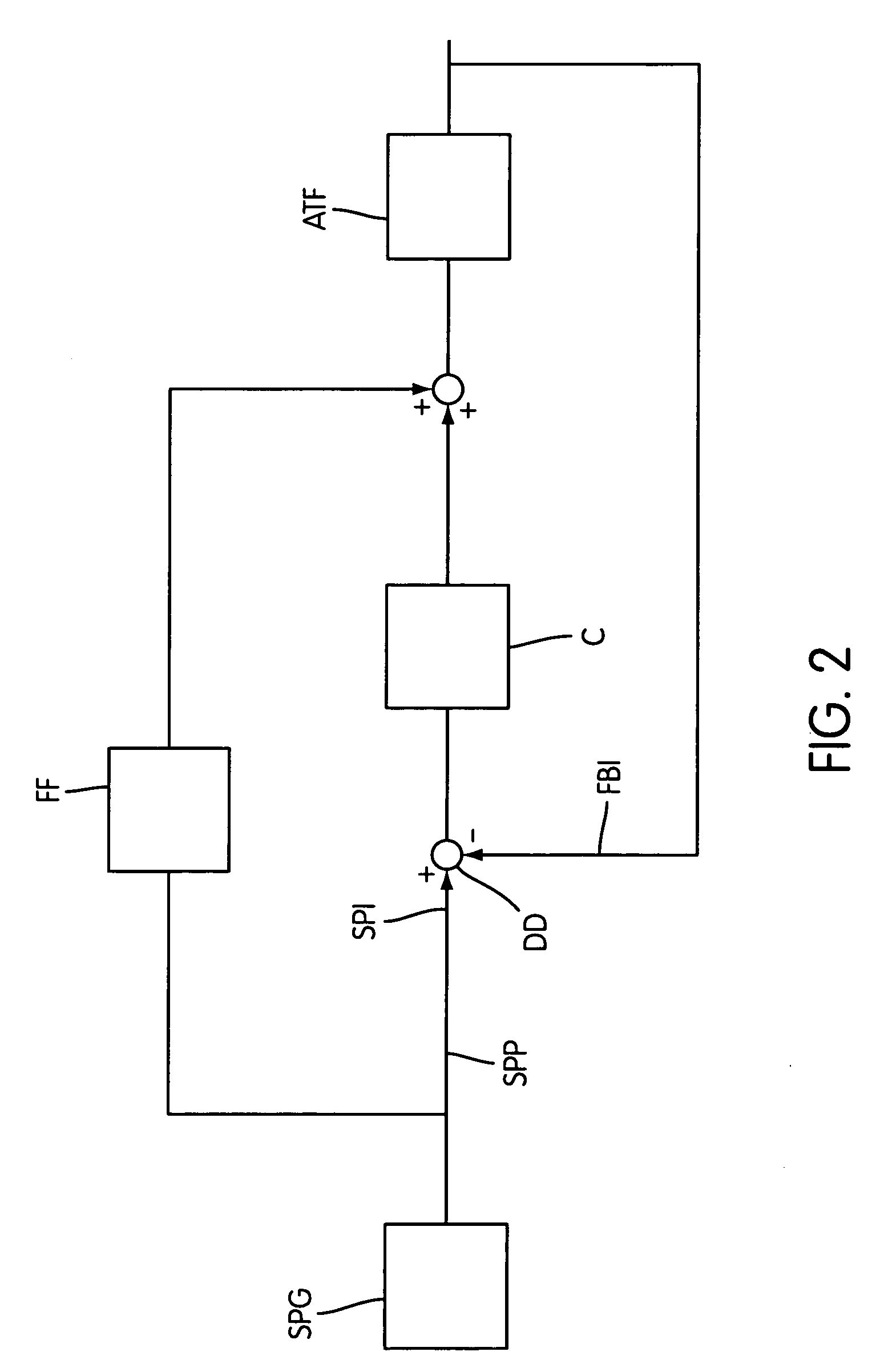
[0060]FIG. 2 depicts a control system comprising a feed-forward and a feed-back loop. A setpoint value or setpoint function is created by a setpoint generator SPG. The parameter or quantity to be controlled, or any quantity derivable therefrom, is controlled by an actuator, expressed in FIG. 2 in terms of an actuator transfer function ATF. A feed-forward path is provided from the setpoint to an input of the actuator transfer function ATF. Further, a feed-back control loop is provided, the loop comprising a controller C the actuator transfer function and a difference determiner for determining a difference between a setpoint input SPI and a feed-back input FBI. The feed-back loop accounts for a high accuracy of the control system. The feed-forward path accounts for a fast response of the control system. A dimensioning of the feed-forward transfer function, in combination with a setpoint delay function in the setpoint path SPP will now be explained with reference to FIG. 3.

[0061]FIG. ...


PUM

PropertyMeasurementUnit
wavelengthaaaaaaaaaa

Abstract

A lithographic apparatus comprising a control system, such as a motion control system, is presented. The control system includes an actuator for moving a moveable part, a feed-forward path from a setpoint input of the control system to the actuator, a feed-back loop, a feed-forward transfer function of the feed-forward path having a feed-forward transfer function part which is an inverse of a part of the actuator transfer function having a stable inverse, the actuator transfer function including a part having a stable inverse and a remainder potentially having an unstable inverse. The setpoint path includes a setpoint delay function, and the feed-forward transfer function further includes a second feed-forward transfer function part. A difference in delay between the setpoint delay function and the second feed-forward transfer function part is equal to a delay of the potentially unstable remainder of the actuator transfer function.

Description

BACKGROUND OF THE INVENTION[0001]1. Field of the Invention[0002]The present invention relates to a lithographic apparatus, a method for controlling a parameter of the lithographic apparatus, a control system and a method for dimensioning a transfer function in such a control system or lithographic apparatus.[0003]2. Description of the Related Art[0004]Lithographic apparatus can be used, for example, in the manufacture of integrated circuits (ICs). In such a case, a patterning device may be used to generate a desired circuit pattern corresponding to an individual layer of the IC, and this pattern can be imaged onto a target portion (e.g. comprising one or more dies) on a substrate (silicon wafer) that has been coated with a layer of radiation-sensitive material (resist).[0005]In general, a single substrate will contain a network of adjacent target portions that are successively exposed. Known lithographic apparatus include so-called steppers, in which each target portion is irradiate...

Claims


Application Information

Patent Timeline
Patent Type & Authority Patents(United States)
IPC IPC(8): G05B13/02G03F7/20G05B13/04G05B21/02H01L21/027
CPCG05B21/02G05B13/042
Inventor VAN DONKELAAR, EDWIN TEUNISVAN DEN BIGGELAAR, PETRUS MARINUS CHRISTIANUS MARIA
Owner ASML NETHERLANDS BV
Why Eureka
Try Eureka