System for electromagnetic field conversion

a technology of electromagnetic field and electromagnetic field, applied in the field of electromagnetic field conversion, can solve the problem of absence of sphere and produce defect, and achieve the effect of high mode suppression ratio

Inactive Publication Date: 2007-11-06
DANMARKS TEKNISKE UNIV
View PDF31 Cites 12 Cited by
  • Summary
  • Abstract
  • Description
  • Claims
  • Application Information

AI Technical Summary

Benefits of technology

[0025]It is an important advantage of the present invention that the full effect of an incident light beam may be utilized for exciting a desired mode of a specific waveguide since the illumination of the waveguide end is no longer required to be confined to a part of the waveguide end within which the phase of the mode in question does not change its sign.
[0026]It is another Important advantage that the power of the incident beam may be coupled into one specific mode and not others whereby a high mode suppression ratio may be achieved.
[0027]The electromagnetic radiation may be of any frequency range of the electromagnetic spectrum, i.e. the gamma frequency range, the ultraviolet range, the visible range, the infrared range, the telecommunication band or bands, the far infrared range, the X-ray range, the microwave range, the HF (high frequency) range, etc.
[0028]Preferably, the electromagnetic radiation is generated by a coherent source of electromagnetic radiation, such as a laser, a semi-conductor laser, a strained multi-quantum well laser, a vertical cavity surface emitting laser (VCSEL), a maser, a phase-locked laser diode array, a light emitting diode, a pulsed laser, such as a sub-picosecond laser, etc. However a high pressure arc lamp, such as a Hg lamp, a Xe lamp etc, may also be used and even an incandescent lamp may be used as a source of electromagnetic radiation.
[0029]The complex spatial electromagnetic field converter may modulate an impinging field by reflection, refraction, or diffraction or any combination hereof, Further, the complex spatial electromagnetic field converter may modulate phase, amplitude, polarization, or mode field diameter, or any combination hereof.
[0030]The complex spatial electromagnetic field converter may comprise a refractive element, such as a refractive element with a surface structure providing the desired phase modulation, e.g. a surface etched structure, or a lenslet array, a ball lens, a semi-ball lens, an aspheric lens or a lens that is not circular symmetric, an-amorphic optics, mirrors that are deformed to provide the desired phase modulation, a refractive phase plate, a GRIN (graded index) material, beamsplitter, etc.

Problems solved by technology

For example, in a three-dimensional photonic crystal formed by dielectric spheres at the sites of a diamond lattice, the absence of a sphere produces a defect.

Method used


Image

  • System for electromagnetic field conversion
  • System for electromagnetic field conversion
  • System for electromagnetic field conversion

Examples


Embodiment Construction

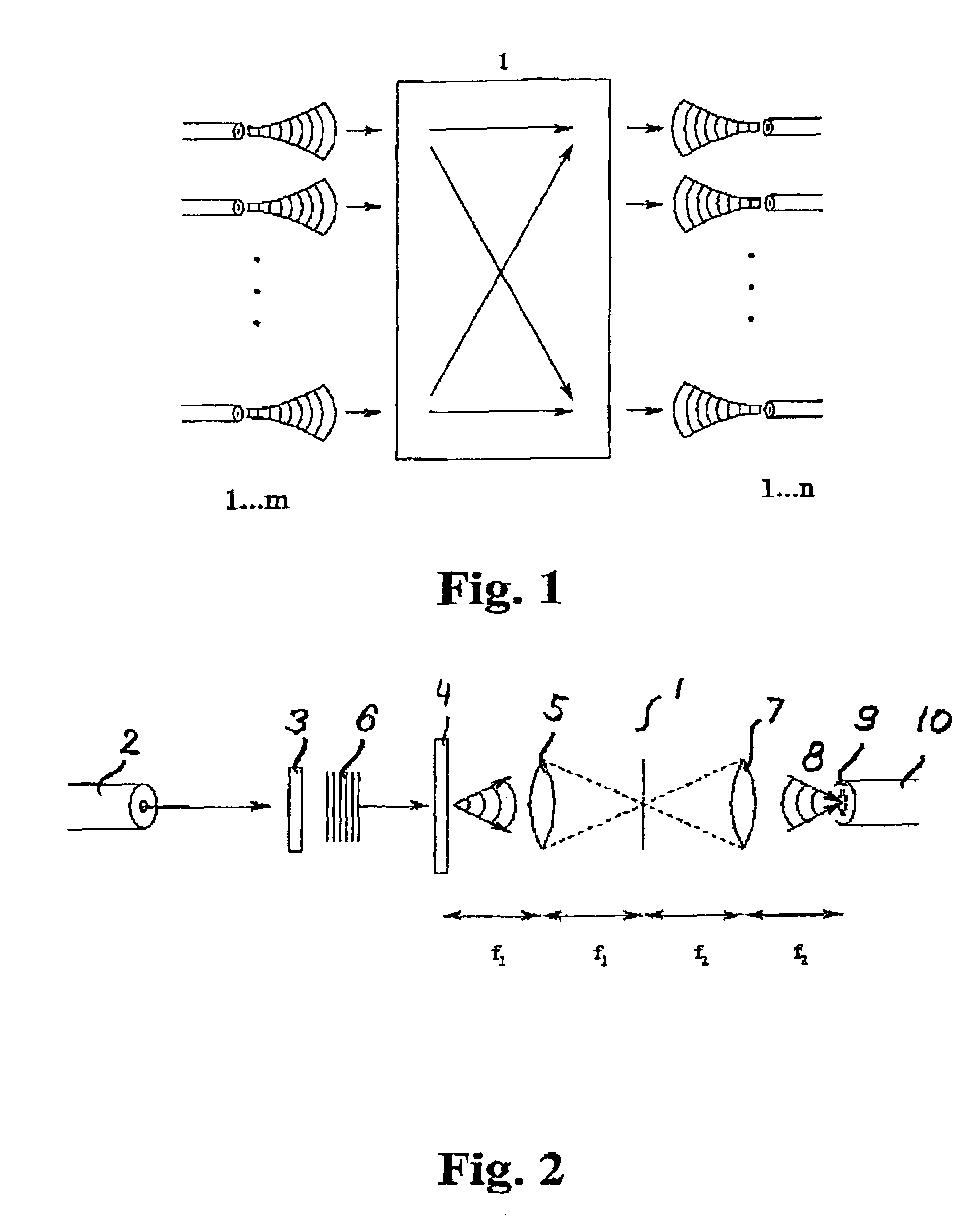
[0062]FIG. 1 illustrates the general principle of the present invention wherein the first electromagnetic field is generated by superposition of electromagnetic fields emitted from a first set of waveguides 1, 2, . . . , m. The system 1 comprising the complex spatial electromagnetic field converter converts the first electromagnetic field into the desired second electromagnetic field that is the superposition of desired propagating modes of a second set of waveguides 1, 2, . . . , n. The system operates to perform both mode conversion and switching.

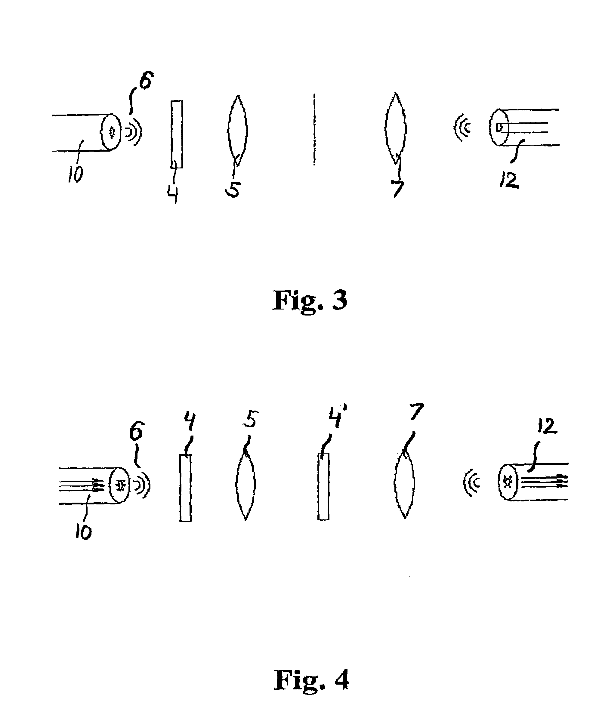
[0063]FIG. 2 shows a 4f optical system 1 for conversion of a first electromagnetic field 6, namely a light beam emitted by a laser 2 and collimated by the collimator 3, into a desired second electromagnetic field 8 for propagation through the microstructured waveguide 10. A complex spatial electromagnetic field converter 4, such as a spatial light modulator (SLM), is positioned for reception of the first electromagnetic field 6 that is tr...


PUM

PropertyMeasurementUnit
mode sizeaaaaaaaaaa
mode sizeaaaaaaaaaa
electromagnetic fieldsaaaaaaaaaa

Abstract

A system is provided for conversion of a first electromagnetic field into a desired second electromagnetic field, for example for coupling modes between waveguides or into microstructured waveguides. The system includes a complex spatial electromagnetic field converter that is positioned for reception of at least a part of the first electromagnetic field and that is adapted for conversion of the received field into the desired electromagnetic field, and wherein at least one of the first and second fields matches a mode of a microstructured waveguide. An advantage of the system is that the full effect of an incident light beam may be utilized for exciting a desired complicated mode of a specific waveguide. Another advantage is that the power of the incident beam may be coupled into one specific mode and not others, whereby a high mode suppression ratio may be achieved.

Description

[0001]This application claims the benefit under 35 U.S.C. 119(e) of U.S. Provisional Application No. 60 / 329,497, filed on Oct. 17, 2001, and U.S. Provisional Application No. 60 / 339,104, filed on Dec. 13, 2001.FIELD OF THE INVENTION[0002]The present invention relates to a system for conversion of a first electromagnetic field to a desired second electromagnetic field, for example for coupling of an electromagnetic field into an electromagnetic waveguide.BACKGROUND OF THE INVENTION[0003]In order to couple light emitted by a light emitting diode or a semiconductor laser into an optical fiber, such as a single mode fiber, it is well known to use a butt coupling or a lens coupling. The butt coupling is a direct coupling Wherein the fiber is brought close to the light source. The butt coupling provides only about 10% efficiency for a laser, as it makes no attempt to match the mode sizes of the laser and the fiber. For example, the laser mode size may be about 1 μm and the mode size of a s...

Claims


Application Information

Patent Timeline
Patent Type & Authority Patents(United States)
IPC IPC(8): G02B6/26G02B6/00G02B6/02G02B6/032G02B6/14G02B6/32G02B6/42G02B26/08G02B27/09G02F1/01
CPCG02B6/02347G02B6/264G02B6/4206G03H1/265G03H2001/0434G02B6/32
Inventor GLUCKSTAD, JESPERSORENSEN, THORKILD
Owner DANMARKS TEKNISKE UNIV
Why Eureka
Try Eureka