Roller assembly for floating dock

a floating dock and roller technology, applied in the field of floating docks, can solve the problems of keel or hull damage, roller wearout or damage, affecting the orientation of the boat, etc., and achieve the effect of less surface contact, easy docking and launching, and reduced assembly stress

Active Publication Date: 2007-11-13
HYDROHOIST INTERNATIONAL INC
View PDF11 Cites 29 Cited by
  • Summary
  • Abstract
  • Description
  • Claims
  • Application Information

AI Technical Summary

Benefits of technology

[0006]In accordance with the invention, a roller assembly is provided for facilitating travel of a watercraft hull on a floating dock. The dock has a longitudinal valley for receiving the keel of the watercraft and a pair of ridges flanking the valley for supporting opposite sides of the hull during docking and launching of the craft on and from the dock. The roller assembly includes a pocket disposed in one of the ridges. A wheel mounted in the pocket rotates about the mid-portion of an axle. The wheel is oriented in the ridge with its circumferential plane parallel to the direction of motion of the watercraft. The upper portion of the wheel protrudes above the crest of the ridge. The axle end bearing portions are co-operable with seats in the pockets to list the circumferential plane toward the valley. It is most desirable that the circumferential plane of the wheel be approximately perpendicular to the face of the hull that it will support. The extent of the protrusion of the wheels above the ridge and the degree of list can be adjusted by use of shims between the pocket seats and the axle end bearing portions. Greater protrusion results in less surface contact between the hull and the dock, making docking and launching easier. Perpendicularity of the wheel circumferential plane to the hull surface reduces stress on the assembly. Two or more such roller assemblies can be spaced apart longitudinally in one or both of the ridges, preferably in opposite relationship across the valley.
[0007]The watercraft hull and bow receiving surfaces of the floating dock should, as in known docks, have a coefficient of friction suitable to permit easy sliding of the watercraft onto the dock. In order to stop the travel of a docking watercraft once it is fully loaded onto the dock, a brake consisting of a seat and stop is provided at the bow portion of the dock. The seat is integrally formed in a portion of the bow-receiving surface of the dock. The stop has an upper surface contoured to receive a portion of the bow of the watercraft and a lower surface contoured to nestle in the seat. The upper surface of the stop has a coefficient of friction substantially greater than the coefficient of friction of the hull and bow receiving surfaces of the dock so as to more rapidly slow the sliding watercraft to a stop.

Problems solved by technology

This orientation has some undesirable results.
First, the majority of the weight of the watercraft on the dock may be borne by the single roller.
Typically, the roller quickly wears out or is damaged or destroyed.
Sometimes, however, the keel or hull will be damaged.
Second, since the roller is concave, if the keel is not properly aligned with the roller during the docking approach, the hull rather than the keel strikes the roller and the roller does not perform in its intended fashion.
Third, since the roller lifts the center of a properly aligned watercraft, the watercraft will list to one side of the dock or even wobble from side to side, depending on the water surface conditions or the distribution of weight on the watercraft.
Fourth, with a single roller at the stern of the dock, when the center of gravity of the watercraft moves forward of the roller, the bow exerts the full weight of the watercraft downwardly onto the dock surface and impedes smooth movement of the watercraft onto or from the dock.
An additional problem associated with known floating docks is that the dock material is selected in part for a low coefficient of friction so that the watercraft hull might slide relatively easily on the dock surface.
Consequently, the more effectively the dock fulfills the docking function, the more likely the bow of the watercraft is to overshoot its intended stopping point on the dock.
This can result in unstable orientation of the watercraft on the dock or in damage to the hull or the dock at their points of impact.
Known connection systems inconveniently require the use of special tools and generally involve the awkward use of these tools underwater to accomplish the connection.

Method used


Image

  • Roller assembly for floating dock
  • Roller assembly for floating dock
  • Roller assembly for floating dock

Examples


Embodiment Construction

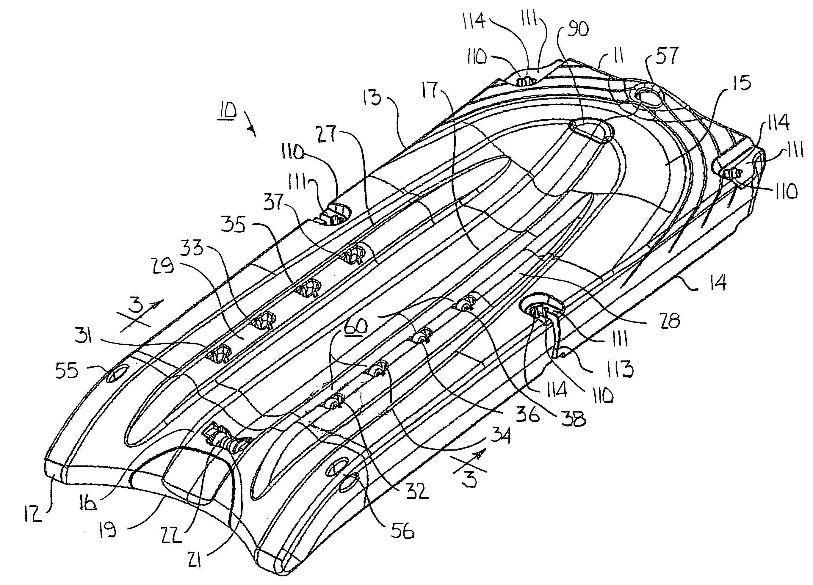
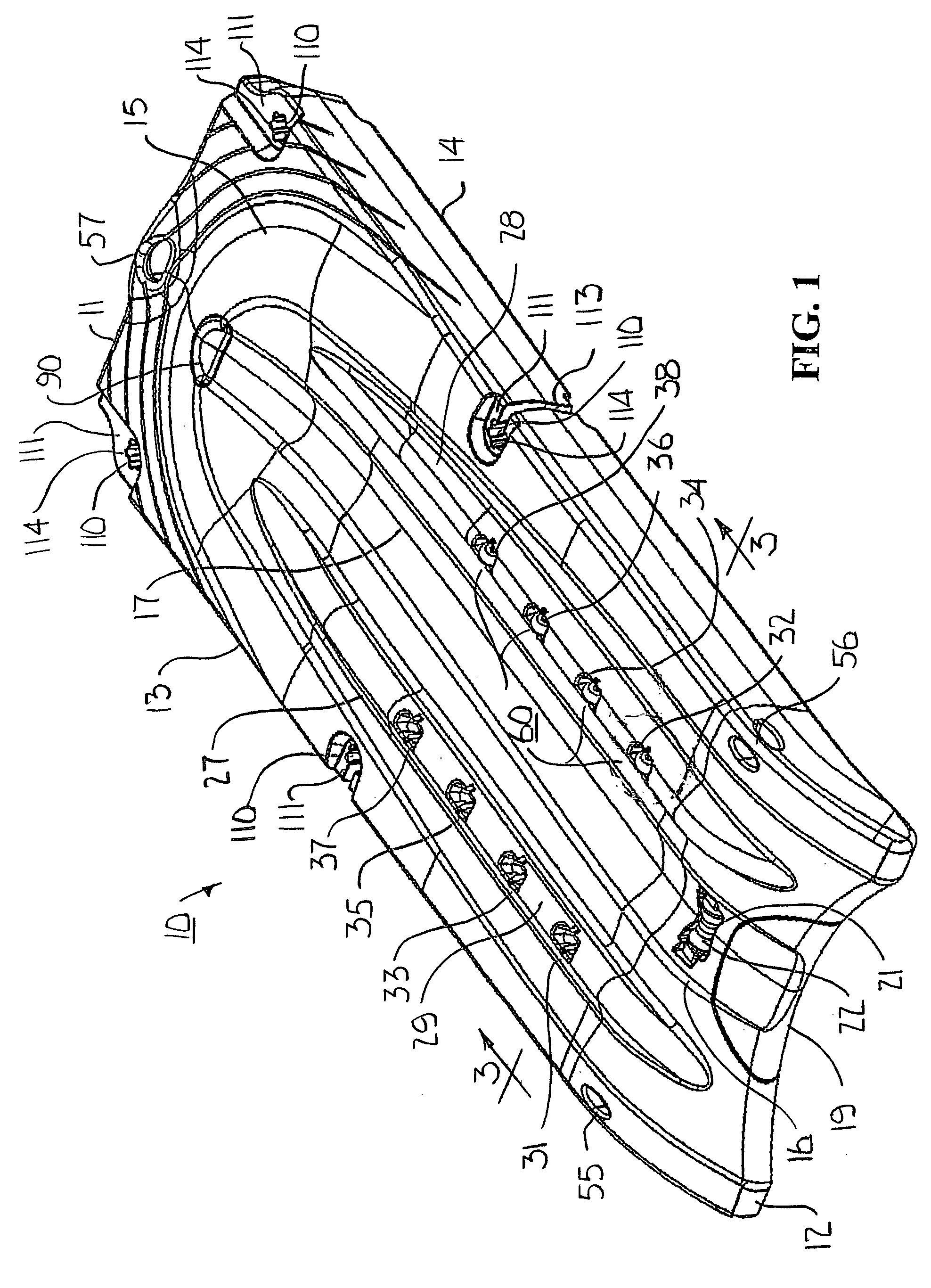
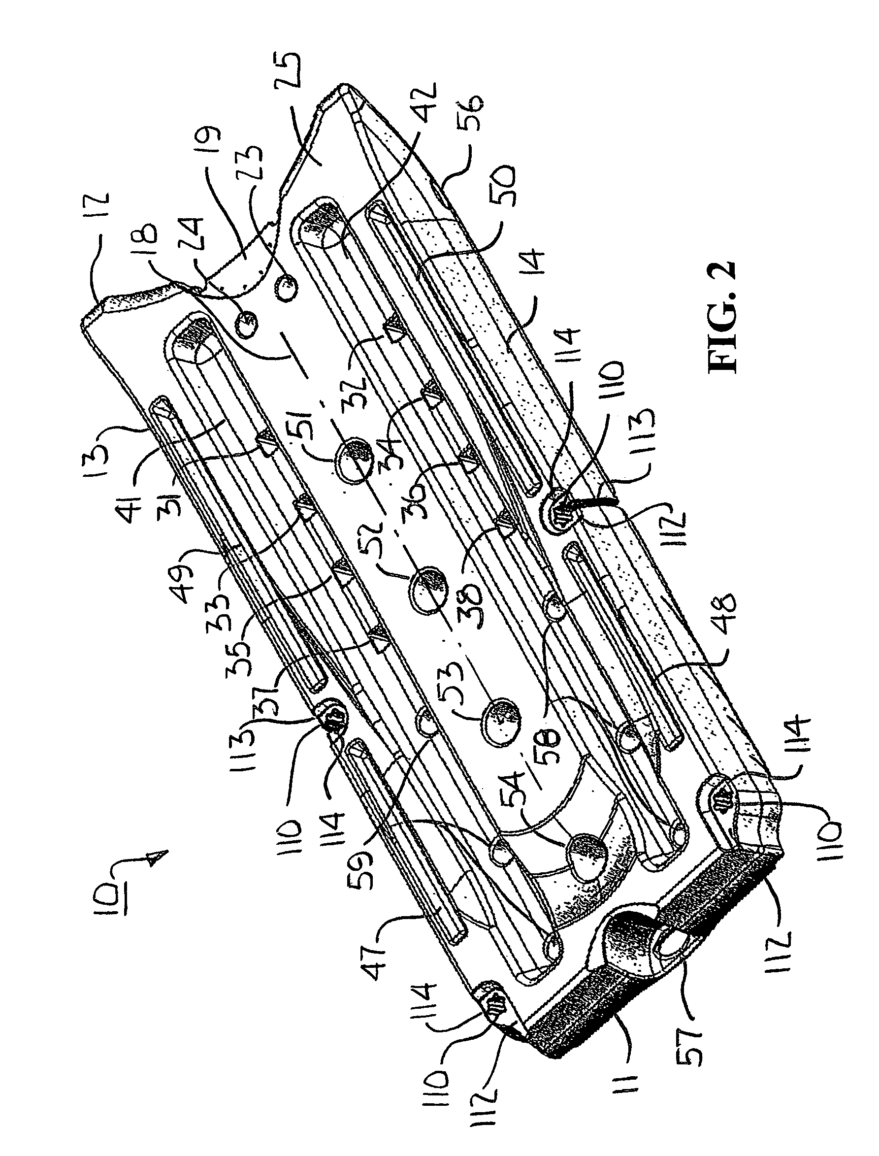
[0027]Turning first to FIGS. 1, 2 and 3, a floating dock 10 is provided for a personal watercraft having a hull which angles upwardly on both sides of its keel at an angle of approximately 16 to 22 degrees above horizontal (not shown). As seen in FIG. 1, the dock 10 has bow and stern walls 11 and 12 and port and starboard sidewalls 13 and 14 defining its perimeter. The perimeter of the dock 10 is generally orthogonal but the stern wall 12 is indented to better receive the arcuate contour of the bow of the watercraft as it makes docking contact with the dock 10. The dock 10 has a top surface 15 contoured for several specific purposes. The stern portion of the top surface 15 tapers downwardly so as to facilitate the docking and launching operations of the watercraft onto and from the dock 10. The top surface 15 has a keel valley 16 with its nadir 17 aligned in a vertical plane through the longitudinal center axis 18 of the dock 10. The stern end of the keel valley 16 includes a remova...


PUM


Abstract

A roller assembly facilitates travel of a watercraft hull on a floating dock having a longitudinal, keel-receiving valley with a pair of flanking ridges supporting opposite sides of the hull during docking and launching of the craft. Pockets in the ridges contain wheels mounted on circumferential planes parallel to the ridges for rotation on axles seated in the pockets. The upper portions of the wheels protrude above the crests of the ridges and the axle end bearing portions cooperate with the seats in the pockets to list the circumferential planes toward the valley and approximately perpendicular to the hull sides. For optimal performance, two or more roller assemblies can be arranged in-line and spaced apart longitudinally in each of the ridges. A brake stops the docking motion of the watercraft onto the dock. Multiple docks can be serially connected without use of special tools or underwater assembly steps.

Description

BACKGROUND OF THE INVENTION[0001]This invention relates generally to floating docks for personal watercraft and more particularly concerns a roller assembly facilitating travel of the watercraft hull on the dock during docking and launching of the craft.[0002]It is fairly common practice to incorporate a single concave roller in the stern end of the keel valley of a floating dock for personal watercraft. The roller is oriented with the expectation that the keel of the watercraft will contact the nadir of the concave surface of the roller during docking and launching of the craft. This orientation has some undesirable results. First, the majority of the weight of the watercraft on the dock may be borne by the single roller. Typically, the roller quickly wears out or is damaged or destroyed. Sometimes, however, the keel or hull will be damaged. Second, since the roller is concave, if the keel is not properly aligned with the roller during the docking approach, the hull rather than the...

Claims


Application Information

Patent Timeline
Patent Type & Authority Patents(United States)
IPC IPC(8): B63B35/44
CPCB63C5/00
Inventor ELSON, TODD A.
Owner HYDROHOIST INTERNATIONAL INC
Why Eureka
Try Eureka