Display using a photoluminescence quenching device, and method for displaying image using the same

a technology of photoluminescence and quenching device, which is applied in the direction of discharge tube luminescnet screens, identification means, instruments, etc., can solve the problems of reducing the life span of projection displays, consuming a large amount of power, and being relatively heavy and large, so as to achieve low optical loss and not heavy and large

Inactive Publication Date: 2007-11-13
SAMSUNG DISPLAY CO LTD
View PDF9 Cites 1 Cited by
  • Summary
  • Abstract
  • Description
  • Claims
  • Application Information

AI Technical Summary

Benefits of technology

[0009]The present invention provides a display which does not require color filters, has low optical losses, and is not heavy and large, and a method for displaying an image using the same. This invention separately provides a display using a photoluminescence quenching device. The display includes a substrate with a plurality of sub-pixels arranged on at least a first side of the substrate, wherein each sub-pixel comprises a first electrode having a first polarity and a second electrode having a second polarity, and an emitter layer, wherein the emitter layer is interposed between the first electrode and the second electrode, the emitter layer receives light projected from an excitation light source, and emits photoluminescence light, and the photoluminescence light from the emitter layer may be controllably quenched by an electrical field formed by the first electrode and the second electrode.

Problems solved by technology

The light intensity used by a CRT is very high, thereby reducing life span of the projection display.
Also, projection displays constructed with CRTs consume a high amount of power and are relatively heavy and large.

Method used


Image

  • Display using a photoluminescence quenching device, and method for displaying image using the same
  • Display using a photoluminescence quenching device, and method for displaying image using the same
  • Display using a photoluminescence quenching device, and method for displaying image using the same

Examples


third embodiment

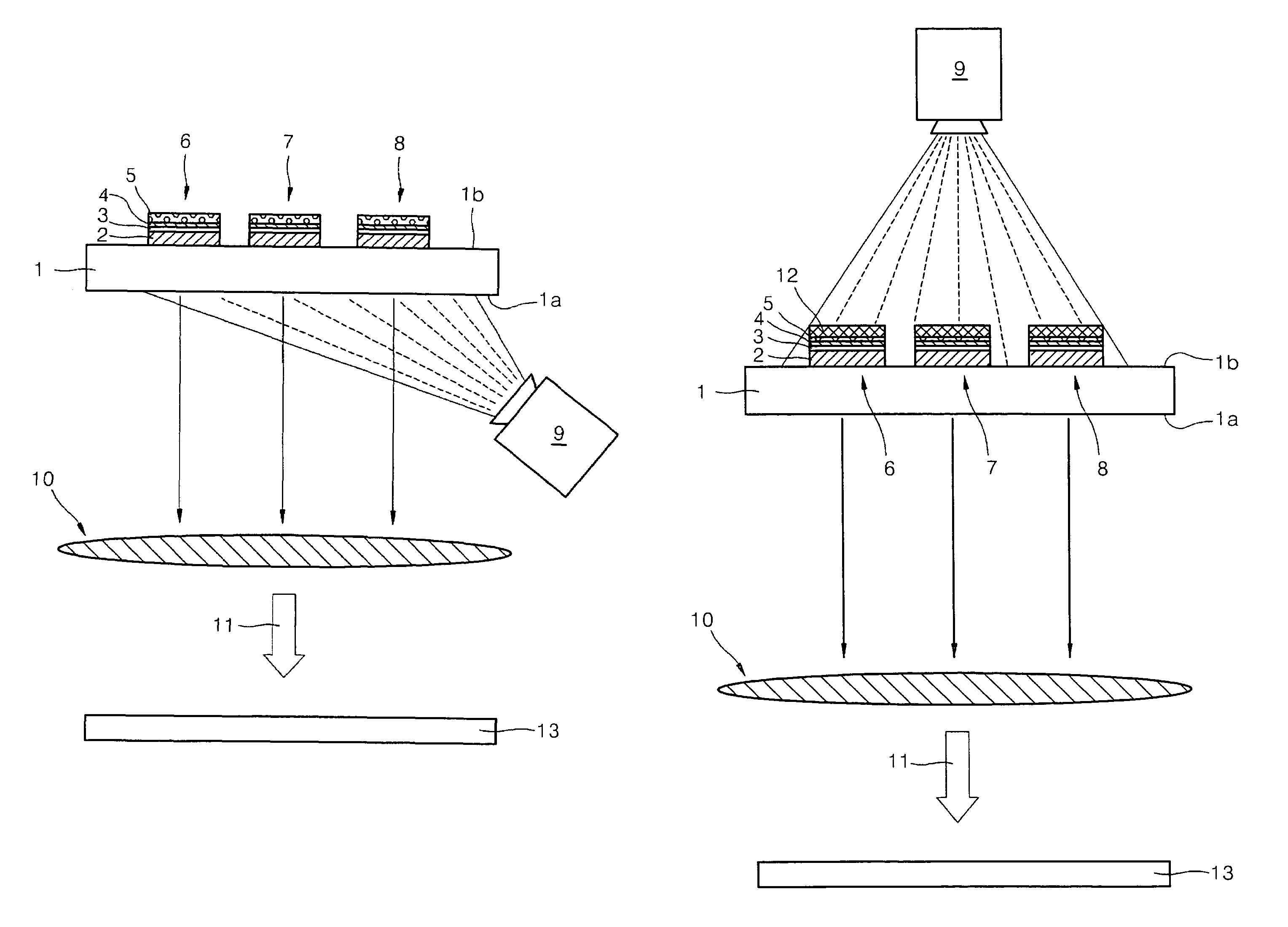
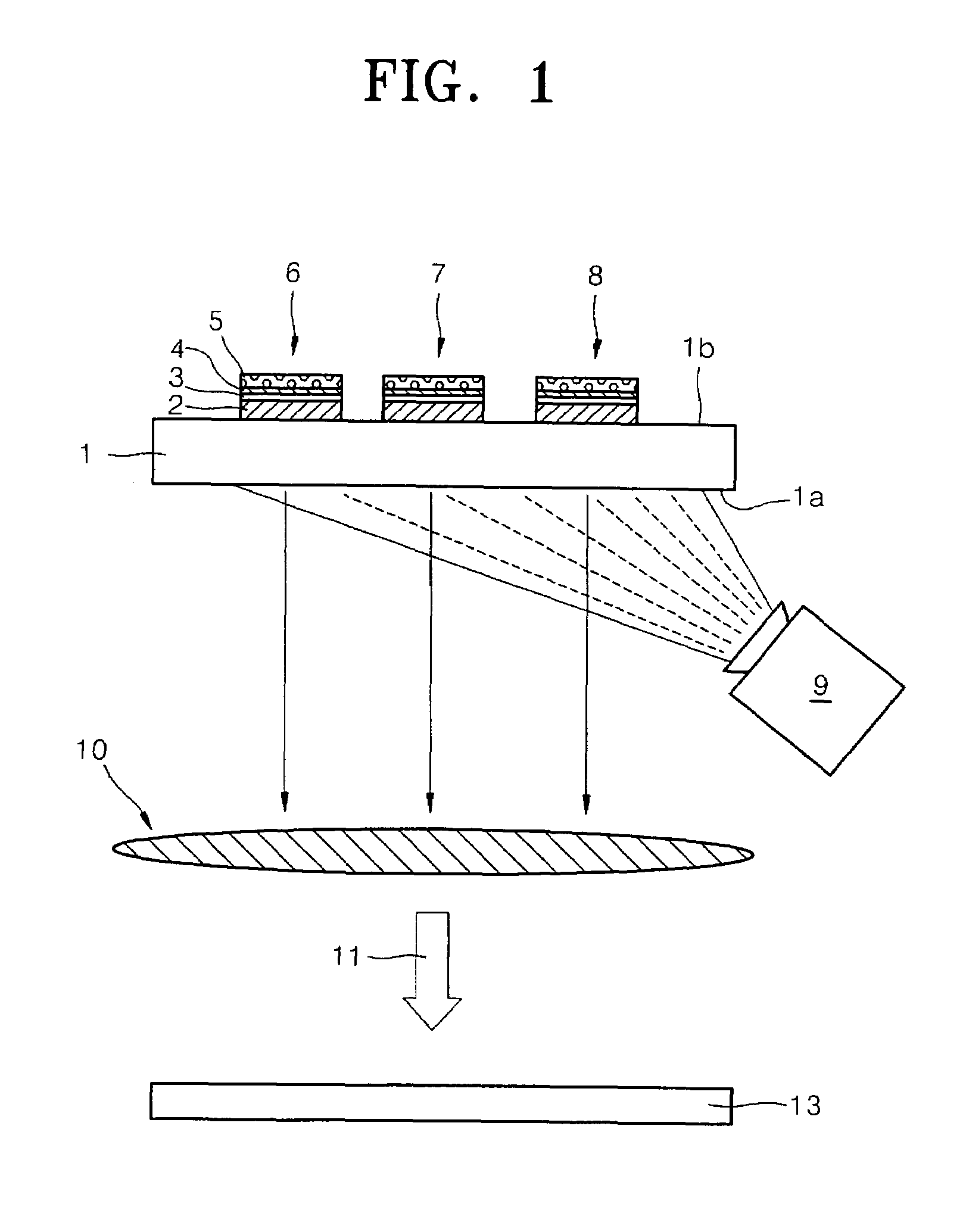
[0034]the present invention will be described with reference to FIG. 3. In the present embodiment, an excitation light source 9 is arranged to project light on a rear side 1b of a substrate 1, and the substrate 1 is formed of a transparent material, and sub-pixels 6, 7, and 8 are arranged on a rear side 1b of the substrate 1. A dielectric mirror 12 is arranged on the sub-pixels 6, 7, and 8. The light emitted from the excitation light source 9 passes through the dielectric mirror 12 and the dielectric mirror 12 reflects light emitted from the emitter layer 4. In this embodiment, the electrodes 2 and 5 are formed of a transparent material.

[0035]In various embodiments of the present invention, the excitation light source 9 may be, for example, a lamp with a high quota of blue light and ultraviolet rays, such as, for example, a mercury lamp and a xenon lamp.

[0036]The dielectric mirror 12 may be formed of a transparent insulating layer which allows light having wavelength in a predetermi...

fourth embodiment

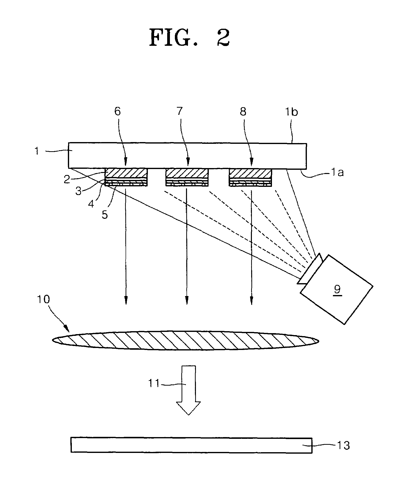
[0039]the present invention will be described with reference to FIG. 4. In the present embodiment, sub-pixels 6, 7, and 8 are arranged on a front side 1a of a substrate 1, and a dielectric mirror 12 which light emitted from an excitation light source 9 passes and reflects light emitted from an emitter layer 4, is arranged between the sub-pixels 6, 7, and 8 and the substrate 1. In this embodiment, electrodes 2 and 5 are formed of a transparent material.

[0040]Light projected from the excitation light source 9 passes through the substrate 1, the dielectric layer 12, and the electrode 2, and reaches the emitter layer 4, thereby causing the emitter layer 4 to radiate photoluminescence light. Light emitted by photoluminescence in the emitter layer 4 is reflected by the dielectric mirror 12, before passing through the electrode 5, and being projected in direction which the front side 1a of the substrate 1 faces.

[0041]The present embodiment allows a process for forming the dielectric mirror...


PUM


Abstract

A display which does not require color filters, has low optical losses, and is not heavy and large, and a method for displaying an image using the display includes a substrate on one side of which sub-pixels are arranged. Each sub-pixel includes two opposite electrodes and an emitter layer which is interposed between the two electrodes. The emitter layer receives the light projected from an excitation light source, and is able to radiate photoluminescence light. The photoluminescence light from the emitter layer may be controllably quenched by an electrical field formed by the electrodes.

Description

CROSS REFERENCE TO RELATED APPLICATIONS[0001]This application claims the priority of European Patent Application 02 090 276.3, filed on Jul. 23, 2002 and Korean Patent Application 2003-8830, filed on Feb. 12, 2003, which are incorporated herein in their entirety by reference.BACKGROUND OF THE INVENTION[0002]1. Field of the Invention[0003]The present invention relates to a display using a photoluminescence quenching device, and a method for displaying an image using the same.[0004]2. Description of the Related Art[0005]Projection displays may be constructed using cathode ray tubes (CRTs) wherein an intermediate image is formed on a phosphor screen by electrical excitation and the intermediate image is projected onto a screen via an optical unit. The light intensity used by a CRT is very high, thereby reducing life span of the projection display. Also, projection displays constructed with CRTs consume a high amount of power and are relatively heavy and large.[0006]Projection displays ...

Claims


Application Information

Patent Timeline
Patent Type & Authority Patents(United States)
IPC IPC(8): H01J1/62H01J63/04G03B21/00G09F9/30G09G3/00H01L51/50H04N9/31
CPCG09G3/002G02F2/02H04N9/31H01L27/3244H01L51/52H10K59/12H10K50/80
Inventor REDECKER, MICHAEL
Owner SAMSUNG DISPLAY CO LTD
Why Eureka
Try Eureka