System and method for improving accuracy in a speckle-based image correlation displacement sensor

a technology of displacement sensor and speckle, applied in the field of displacement sensors, can solve the problems of reducing the signal to noise ratio, reducing system accuracy and repeatability, etc., and achieve the effect of meaningful measurement resolution and/or accuracy, and improving the accuracy of speckle-based image correlation displacement sensors

Active Publication Date: 2007-11-13
MITUTOYO CORP
View PDF17 Cites 32 Cited by
  • Summary
  • Abstract
  • Description
  • Claims
  • Application Information

AI Technical Summary

Benefits of technology

[0007]A system and method for improving the accuracy of a speckle-based image correlation displacement sensor is provided. The systems and methods disclosed herein are particularly useful for reducing or eliminating previously ignored or unrecognized speckle-based image correlation displacement sensor errors that become significant when the system measurement resolution and accuracy reach sub-micron levels. The systems and methods disclosed herein are particularly useful for providing meaningful measurement resolution and / or accuracy on the order of 100 nanometers, 10 nanometers, and even 1 nanometer or less in various speckle-based image correlation displacement sensing systems.
[0008]In accordance with one aspect of the invention, the speckle intensity pattern is stabilized so as to reduce the modulation of individual speckles within the intensity pattern due to causes other than displacement, so as to avoid the correlation function peak value converging toward the correlation function noise value arising from image randomness. In other words, the system is made to have high accuracy by ensuring that, in the absence of motion, the speckle image does not significantly vary over time. This is important because speckle-based image correlation displacement sensors operate by computing the correlation between a reference image (stored in memory) and a current image. The displacement is determined by using interpolation to find the peak of the correlation value curve with sub-pixel accuracy, and in order for the highest accuracy to be obtainable, the image must be stable except for the desired displacement-induced effects. More specifically, for certain sources and / or types of image instability discussed below, the modulation phase for the different speckles within the image tends to be random. In other words, the whole image does not modulate in intensity, but rather, various parts of the image (i.e., individual speckles) modulate with random phase relation to other parts. The effect of this type of instability is to lower the correlation function peak value, that is, reduce the peak height, relative to the noise (not electronic noise, but the inherent correlation function noise arising from the image randomness which produces a nominal non-zero “background” correlation value at offset values away from the peak (or trough) of the correlation curve.) This, in turn, essentially reduces the signal to noise (S / N) ratio of the correlation “signal” and will cause a reduction in the system accuracy and repeatability. Thus, by reducing or eliminating this type of image instability, the accuracy and repeatability of the system can be improved.
[0009]In accordance with another aspect of the invention, the speckle image is stabilized by reducing or compensating for wavelength changes in the coherent light source of the displacement sensor system. The term “light” as used herein means any operable visible or invisible wavelength of radiation. In one embodiment, the coherent light source is a laser diode. Wavelength changes tend to cause image “drift” or speckle spatial phase modulation, thus, accordingly, reducing or compensating for the wavelength changes stabilizes the image.

Problems solved by technology

This, in turn, essentially reduces the signal to noise (S / N) ratio of the correlation “signal” and will cause a reduction in the system accuracy and repeatability.

Method used


Image

  • System and method for improving accuracy in a speckle-based image correlation displacement sensor
  • System and method for improving accuracy in a speckle-based image correlation displacement sensor
  • System and method for improving accuracy in a speckle-based image correlation displacement sensor

Examples


Embodiment Construction

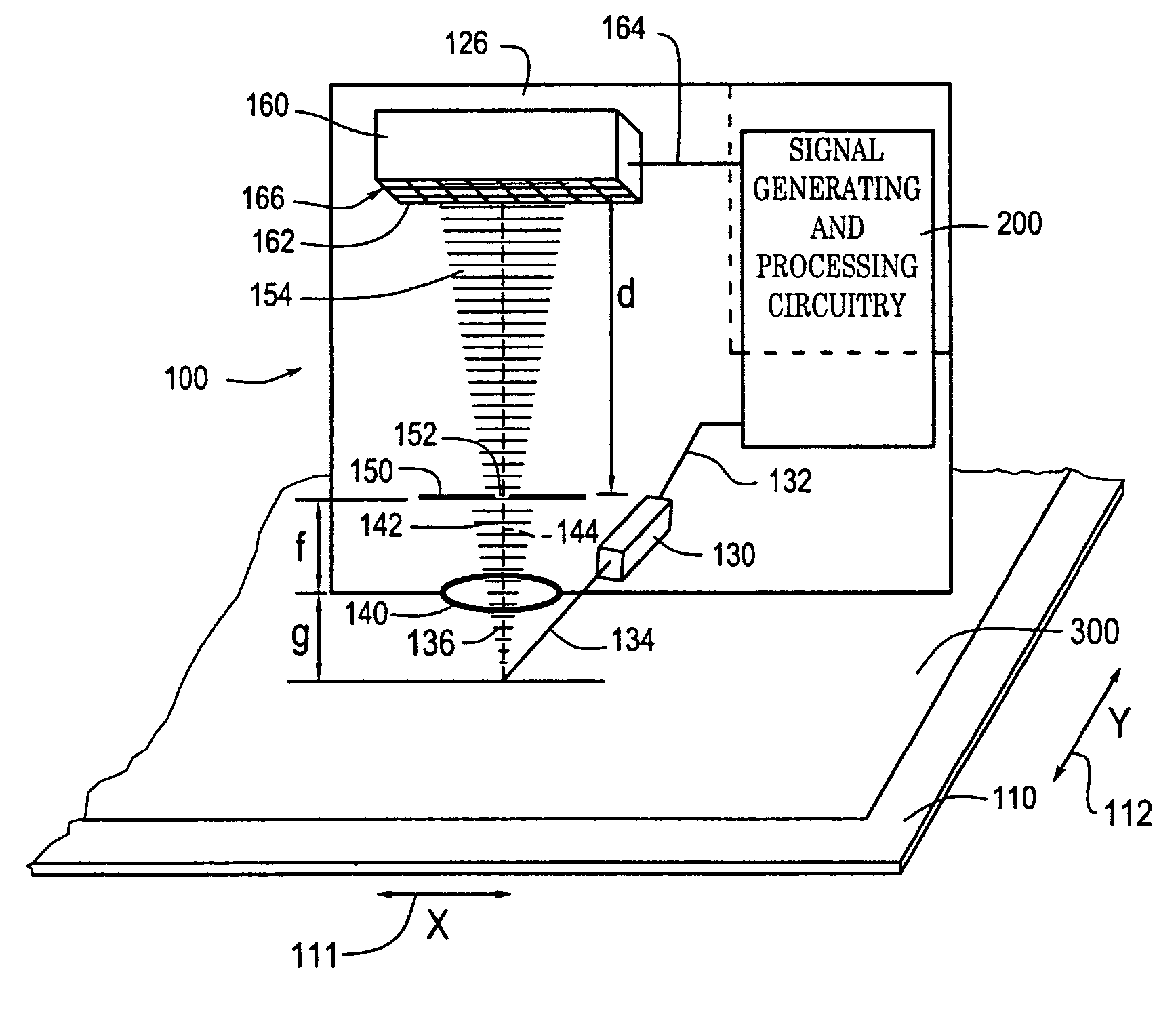
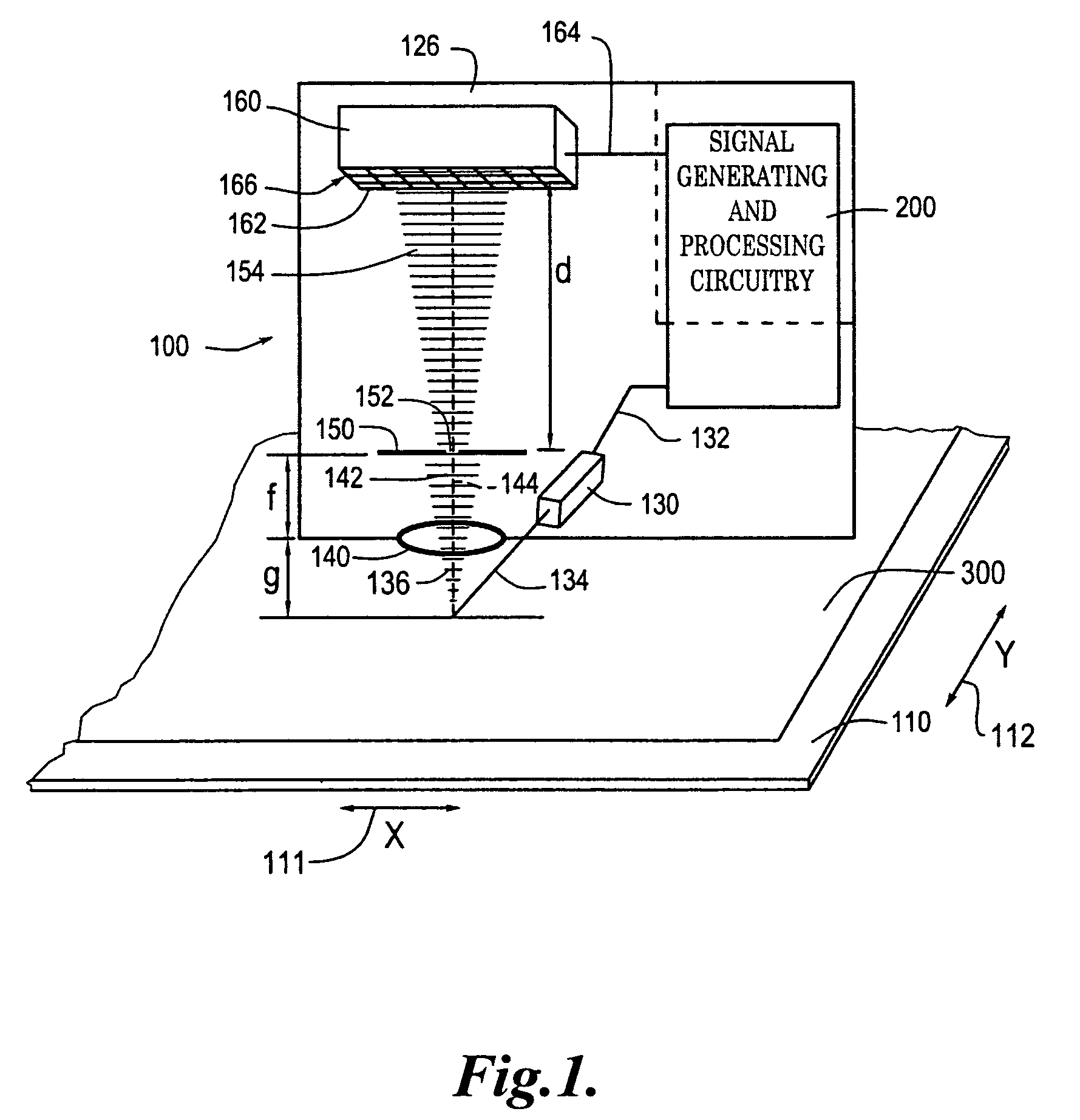
[0047]FIG. 1 is a schematic block diagram of a 2-dimensional (2D) optical displacement sensor 100 usable with an optically diffusing, or optically rough, surface according to this invention to generate a 2D displacement measurement. The 2D optical displacement sensor 100 shown in FIG. 1 includes a readhead 126, signal generating and processing circuitry 200 and a 2D scale 110. The 2D scale 110 includes an optically diffusing, or optically rough, surface 300, which may be integral with and / or indistinguishable from the scale 110, or an added or processed surface. In FIG. 1, the components of the readhead 126, and their relation to the 2D scale 110 and the surface 300, are shown schematically in a layout that generally corresponds to an exemplary physical configuration, as further described below.

[0048]As described in more detail below with reference to FIG. 3, the optically diffusing, or optically rough surface 300 diffracts or otherwise scatters light used to illuminate the surface ...


PUM


Abstract

A system and method for improving the accuracy of a speckle-based image correlation displacement sensor provides ultra-high accuracy by ensuring that, in the absence of motion, the speckle image does not vary over time. In one embodiment, the speckle image is stabilized by reducing or compensating for laser diode wavelength changes. Various methods for stabilizing the wavelength include thermoelectric temperature control, measuring and correcting the wavelength by any suitable means, or providing a specific wavelength of light feedback from an external grating. Image stabilization may also be accomplished by monitoring the warm-up process of the system. Once the system is determined to have completed the warm-up process, an indicator is provided to the user to indicate that the system is ready for use. Sensor geometric configurations that reduce or eliminate wavelength-related errors are also disclosed.

Description

FIELD OF THE INVENTION[0001]This invention is related to displacement sensors, and more particularly to speckle-based image correlation displacement sensors.BACKGROUND OF THE INVENTION[0002]Various known devices use speckle images and correlation between speckle images to determine deformations and / or displacements. A speckle image is generated by illuminating an optically rough surface with a light source. Generally, the light source is a coherent light source, and more particularly, is a laser-generating light source, such as a laser, a laser diode, and the like. After the optically rough surface is illuminated by the light source, the light scattered from the optically rough surface is imaged onto an optical sensor, such as a charge-coupled device (CCD), a semi-conductor image sensor array, such as a CMOS image sensor array, or the like.[0003]Prior to displacement or deformation of the optically rough surface, a first speckle image is captured and stored. Subsequently, after defo...

Claims


Application Information

Patent Timeline
Patent Type & Authority Patents(United States)
IPC IPC(8): G01B9/02
CPCG01B11/002G01D5/34715G01B11/16
Inventor JONES, BENJAMIN K.NAHUM, MICHAEL M.TOBIASON, JOSEPH D.MASRELIEZ, KARL G.
Owner MITUTOYO CORP
Why Eureka
Try Eureka