Device for low-interfernce signal transmission

a low-interferance signal and transmission device technology, applied in the direction of transmission, modulated carrier system, electrical apparatus, etc., can solve the problems of contact-less open transmission system such as linear transmission or rotating transmission, exceeding the limits defined in the common emc standard, and being particularly problemati

Inactive Publication Date: 2007-11-13
SCHLEIFRING & APPBAU
View PDF13 Cites 11 Cited by
  • Summary
  • Abstract
  • Description
  • Claims
  • Application Information

AI Technical Summary

Benefits of technology

[0029]In addition to the modulation by a modulator unit, data codi

Problems solved by technology

This spectrum may result in interfering radiations already in closed or shielded systems, particularly, however, in open systems such as rotating data transmission devices revolving transmitters, which interfering radiation may exceed the limits defined in the common EMC standards.
In this respect contact-less open transmission systems such as tho

Method used


Image

  • Device for low-interfernce signal transmission
  • Device for low-interfernce signal transmission
  • Device for low-interfernce signal transmission

Examples


Embodiment Construction

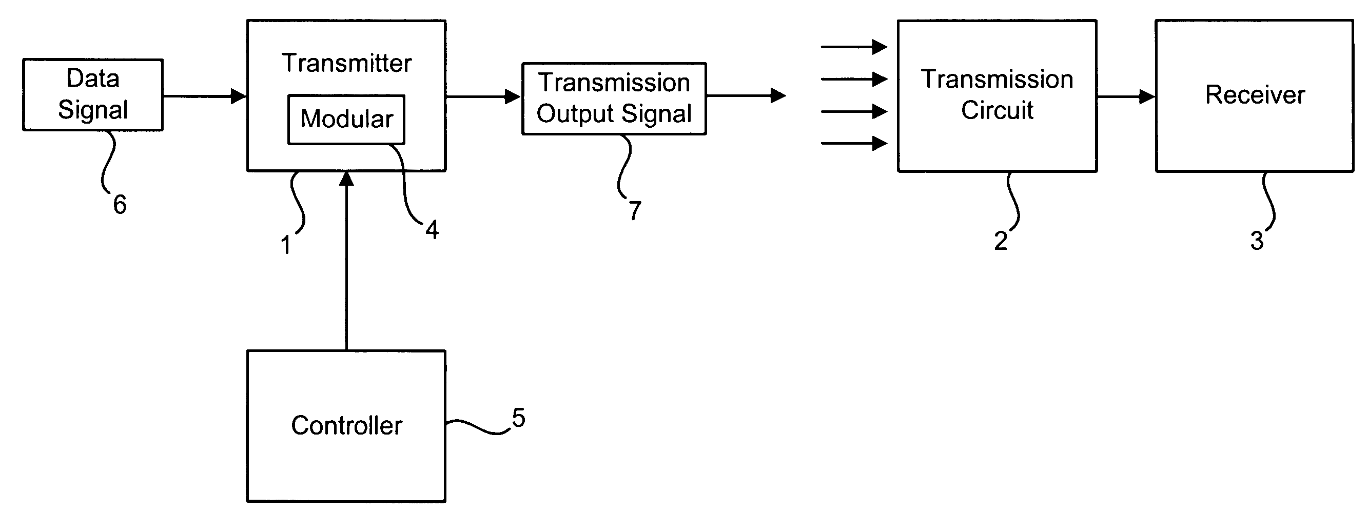
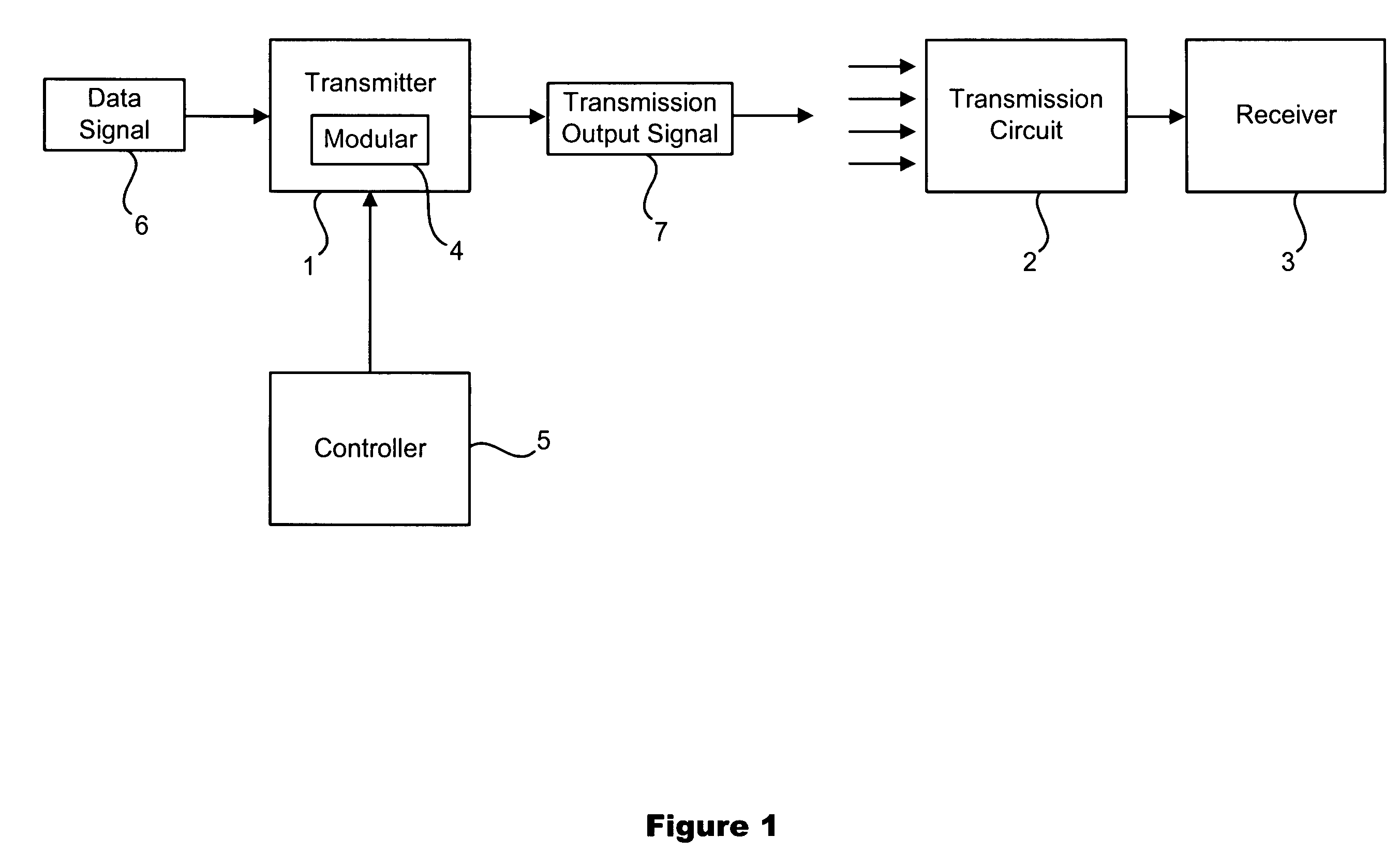
[0059]FIG. 1 shows an inventive system comprising of a transmitter (1) which is connected to the receiver (3) via a transmission circuit (2). The transmitter (1) includes a modulator (4) and is controlled via a controller (5). By means of controller (5) a modulation signal for modulating a data signal (6) or the frequency of the clock generator, respectively, is generated in such a way that the spectrum of the transmitter output signal (7), which is transmitted via the transmission circuit (2), will be spread. For receiver circuits corresponding to prior art a slight modulation, particularly a frequency modulation of the data signal (6), is no problem. The modification of the frequency, particularly at a low modulation frequency, is finely controlled, without any problem, by the PLL provided in receiver (3) for data and cycle reconstruction.

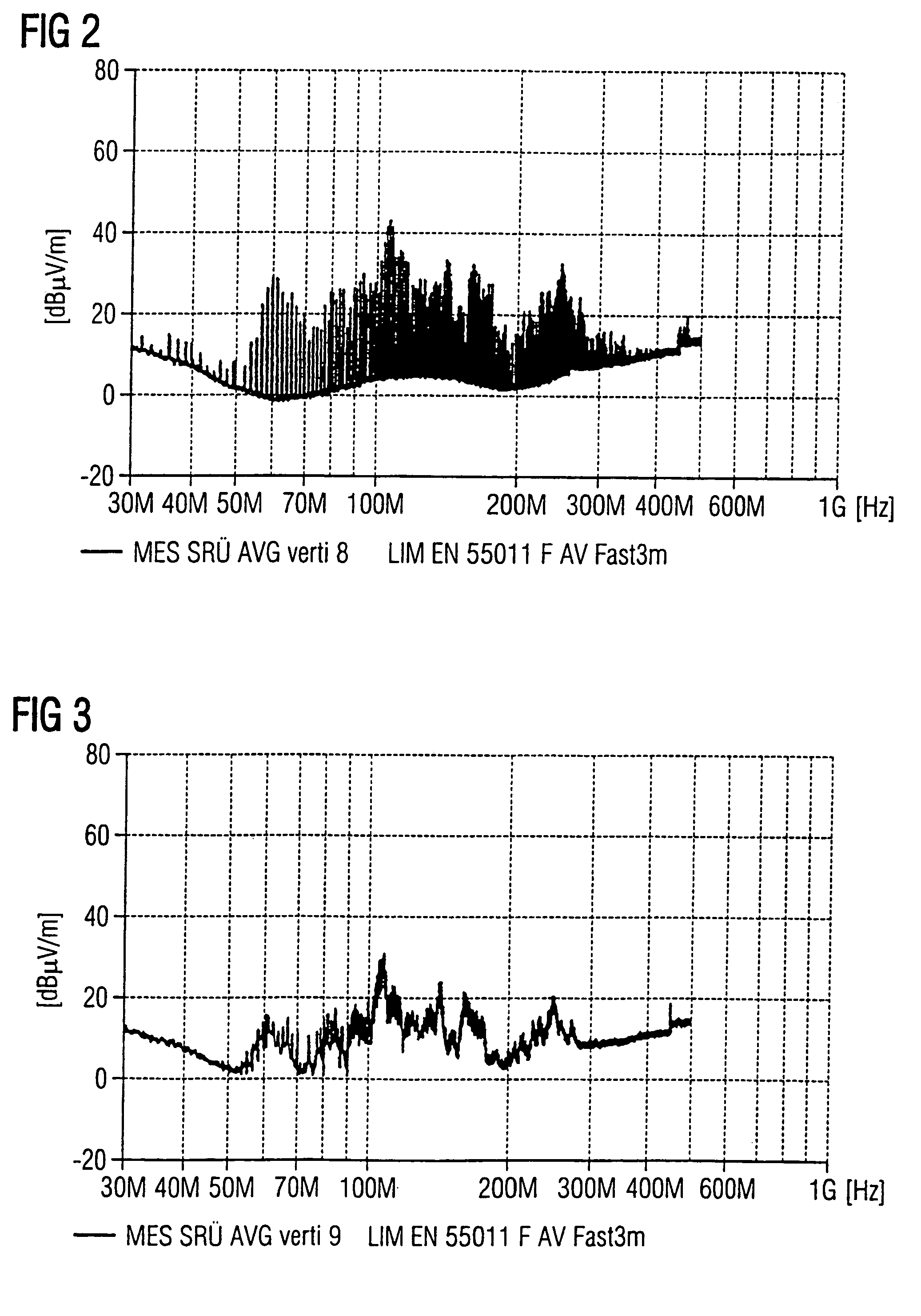
[0060]FIG. 2 shows the spectrum measured in an absorber hall, which is emitted by a transmitter corresponding to prior art via the data circuit ...


PUM


Abstract

Digital signal transmitter devices mostly present a distinct wide-band interference spectrum which renders compliance with the presently applicable EMC standards substantially more difficult.
Available provisions for improving the EMC characteristics take an influence on the quality in transmission and on the immunity to interference.
By the inventive method the carrier signal or output signal, respectively, of the transmitter is so modulated that the narrow spectral lines are spread and the spectral power density is reduced.

Description

FIELD OF THE INVENTION[0001]The present invention relates to a device for or a method of improving the electromagnetic compatibility (EMC) of data circuits and of digital data circuits in particular.PRIOR ART[0002]The applications of digital data circuits are continuously expanding. In the majority of cases the digital signal transmission presents significant advantages over analog signal transmission. The costs of high-speed data channels are reduced by the development of new transmission techniques. The width of the individual channels has become very inexpensive so that multiplexing of several low-rate signal circuits to form a single high-speed signal circuit is often the most economic solution. This has been implemented particularly in high speed rotary joints.[0003]The conventional solution for the transmission of high data volumes from rotating parts to stationary parts has been the parallel application of a large number of slip ring paths. This resulted in a solid structure ...

Claims


Application Information

Patent Timeline
IPC IPC(8): H04B1/69H04B1/707H04B15/04H04L25/28
CPCH04B15/04H04B2215/067
Inventor LOHR, GEORG
Owner SCHLEIFRING & APPBAU
Why Eureka
Try Eureka