Radial antenna and plasma device using it

Inactive Publication Date: 2007-11-20
TOKYO ELECTRON LTD
View PDF3 Cites 4 Cited by
  • Summary
  • Abstract
  • Description
  • Claims
  • Application Information

AI Technical Summary

Benefits of technology

[0009]In order to achieve the above object, a radial antenna according to the present invention is characterized by comprising a first conductive plate in which a plurality of slots are formed, a second conductive plate having a microwave inlet and disposed opposite to the first conductive plate, a ring member for connecting peripheral edges of the first and second conductive plates, and a conductive adjusting member provided on the second conductive plate in a radial waveguide formed by the first and second conductive plates and serving to adjust a distance up to the first conductive plate. When the distance from the second conductive plate to the first conductive plate is decreased, the power density between the first and second conductive plates can be increased. Thus, even when the slot length of slots formed in the first conductive plate is decreased to be sufficiently smaller than a length corresponding to λg / 2, the radiated electric field strength can be increased.
[0012]In the radial antenna descried above, when the slots are substantially rectangular or arcuate, the slot length is preferably decreased to be smaller than a length corresponding to λg / 3. Then, even if the widths of the slots are narrow, induction of abnormal discharge can be prevented effectively.

Problems solved by technology

If, however, the width W2 is excessively small, it may cause abnormal discharge.

Method used


Image

  • Radial antenna and plasma device using it
  • Radial antenna and plasma device using it
  • Radial antenna and plasma device using it

Examples


first embodiment

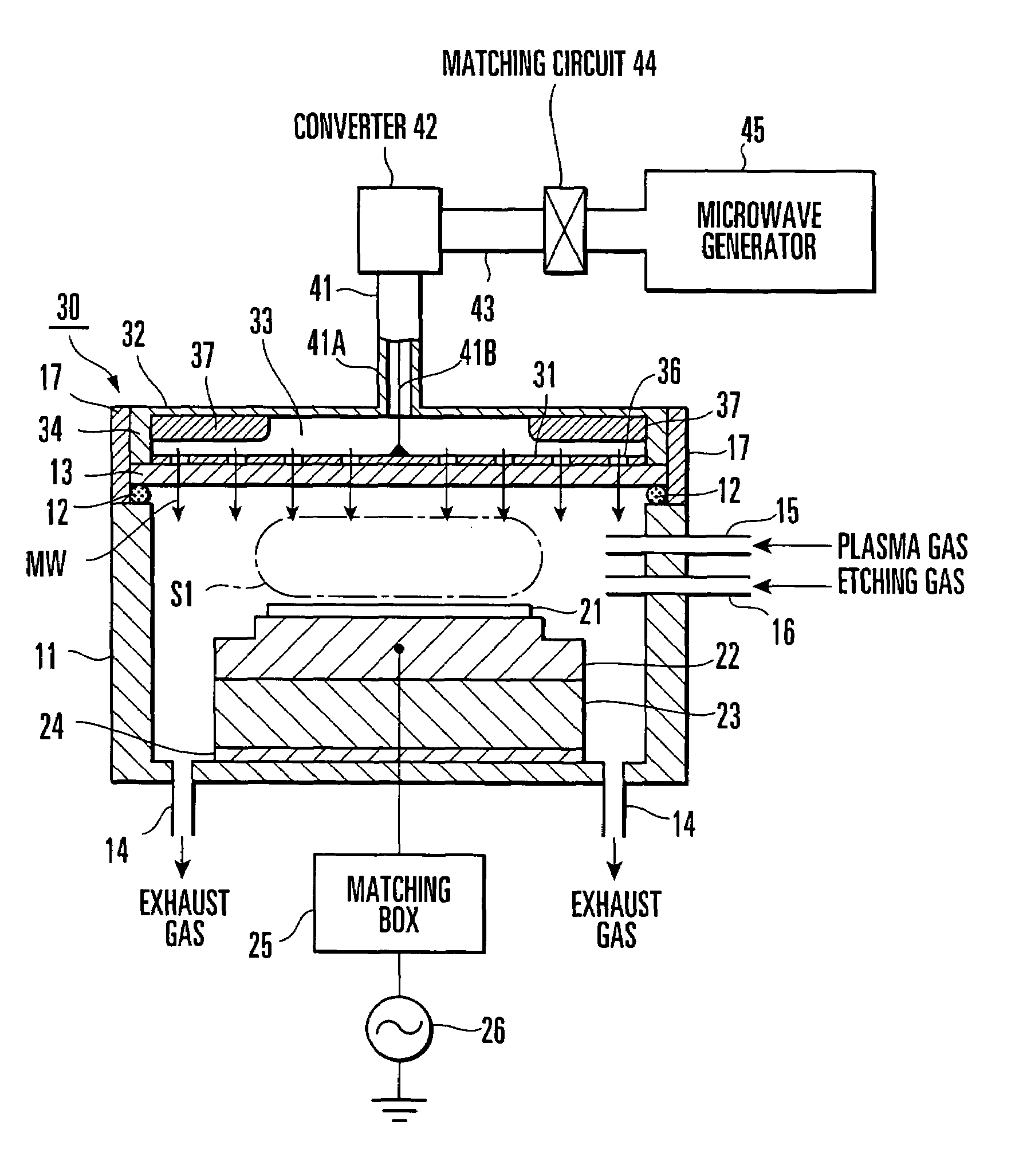
[0023]FIG. 1 is a view showing the arrangement of an etching apparatus according to the first embodiment of the present invention. In FIG. 1, the sectional structure of part of the arrangement is shown.

[0024]The etching apparatus shown in FIG. 1 has a cylindrical processing vessel 11 with an upper opening. This processing vessel 11 is made of a conductive member such as aluminum.

[0025]Exhaust ports (exhaust means) 14 communicating with a vacuum pump (not shown) are formed in the bottom of the processing vessel 11, so the interior of the processing vessel 11 can be evacuated to a predetermined vacuum degree.

[0026]A plasma gas supply nozzle 15 for introducing a plasma gas such as Ar into the processing vessel 11, and a process gas supply nozzle 16 for introducing an etching gas are formed in the upper and lower portions, respectively, of the side wall of the processing vessel 11. The nozzles (gas supply means) 15 and 16 are formed of quartz pipes or the like.

[0027]The processing vesse...

second embodiment

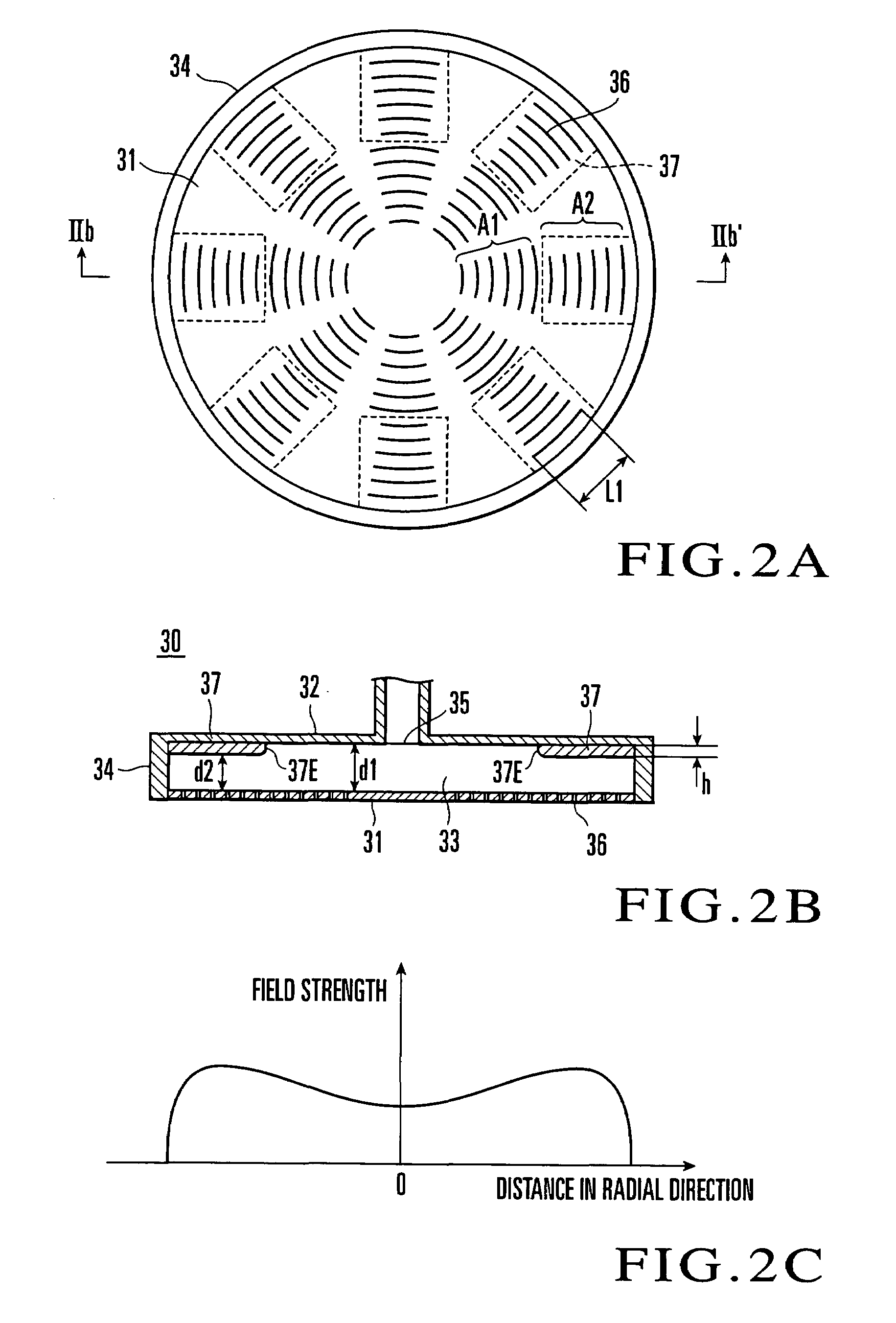
[0053]In the radial antenna 30 shown in FIG. 2, the ridges 37 are disposed radially. Alternatively, the ridges may be disposed along the periphery of the conductive plate 32. FIG. 6 includes views showing the arrangement of a radial antenna in which ridges are disposed in this manner. FIG. 6(a) is a plan view showing the radiation surface of the radial antenna, and FIG. 6(b) is a sectional view taken along the line VIb-VIb′ of FIG. 6(a). FIG. 6(a) is shown conceptually to clarify the characteristic feature of the present invention. In FIG. 6, the same portions as in FIG. 2 are denoted by the same reference numerals, and a description thereof will be omitted as required.

[0054]As shown in FIG. 6, three ridges 137A, 137B, and 137C serving as adjusting members are fixed along the periphery of the lower surface of a conductive plate 32 in a radial waveguide 133. The ridges 137A to 137C form concentric circles conforming to the periphery of the conductive plate 32, and are disposed in thi...


PUM

PropertyMeasurementUnit
Lengthaaaaaaaaaa
Electrical conductoraaaaaaaaaa
Electric fieldaaaaaaaaaa

Abstract

A plasma device includes a first conductive plate (31) in which a plurality of slots (36) are formed, a second conductive plate (32) having a microwave inlet (35) and disposed opposite to the first conductive plate (31), a ring member (34) for connecting peripheral edges of the first and second conductive plates (31, 32), and a conductive adjusting member (37) provided on said second conductive plate (32) within a radial waveguide (33) formed by the first and second conductive plates (31, 32) and serving to adjust a distance (d1, d2) up to the first conductive plate (31). With this arrangement, a desired electric field radiation distribution can be obtained without inducing abnormal discharge.

Description

BACKGROUND OF THE INVENTION[0001]The present invention relates to a radial antenna and a plasma device using it.[0002]In the manufacture of a semiconductor device, plasma devices are used often to perform processes such as formation of an oxide film, crystal growth of a semiconductor layer, etching, and ashing. Among the plasma devices, a microwave plasma device is available which produces a high-density plasma by introducing a microwave into a processing vessel through a radial antenna. As a characteristic feature of the microwave plasma device, it has wide applications because it can stably produce a plasma even if the pressure is comparatively low.[0003]FIG. 7 includes views showing the arrangement of an example of a radial antenna conventionally used in the microwave plasma device, and the distribution of its electric field radiation. FIG. 7(a) is a conceptual view showing the radiation surface of the radial antenna, FIG. 7(b) is a sectional view taken along the line VIIb-VIIb′ ...

Claims


Application Information

Patent Timeline
IPC IPC(8): C23C16/00B01J19/08H05H1/46H01J37/32H01L21/205H01L21/302H01L21/3065
CPCH01J37/3222H01J37/32192
Inventor ISHII, NOBUOSHINOHARA, KIBATSU
Owner TOKYO ELECTRON LTD
Why Eureka
Try Eureka