Oil-sorbing filter element

a filter element and oil-sorbing technology, applied in the direction of filtration separation, other chemical processes, separation processes, etc., can solve the problems of premature shortened service life of filters and media of such types

Active Publication Date: 2007-11-20
PARKER INTANGIBLES LLC
View PDF24 Cites 14 Cited by
  • Summary
  • Abstract
  • Description
  • Claims
  • Application Information

AI Technical Summary

Problems solved by technology

It has been observed, however, that media of such type may not always perform optimally due to settling of the medium within the canister or other housing within which it may be contained, or due to channelin

Method used


Image

  • Oil-sorbing filter element
  • Oil-sorbing filter element
  • Oil-sorbing filter element

Examples


Embodiment Construction

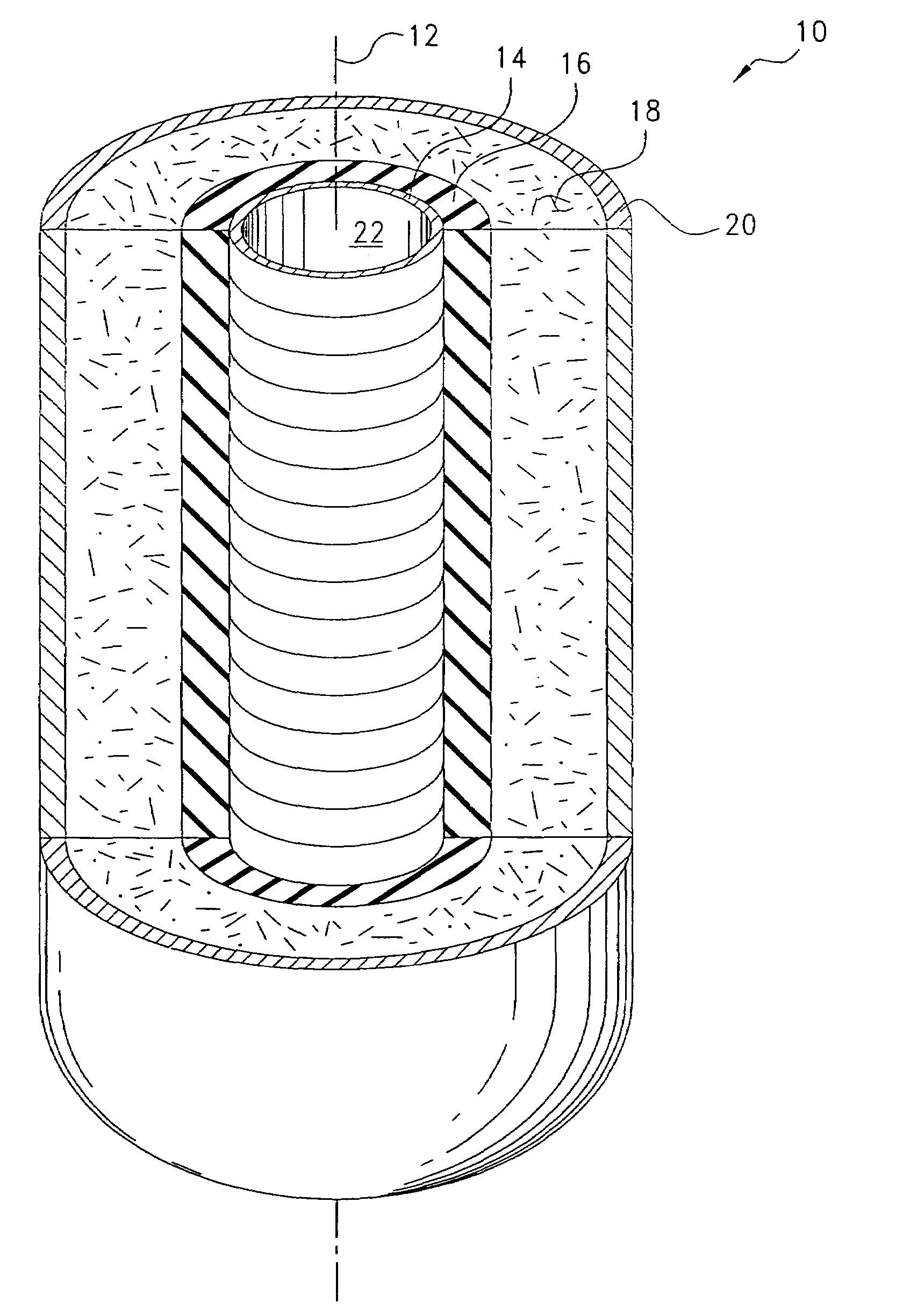
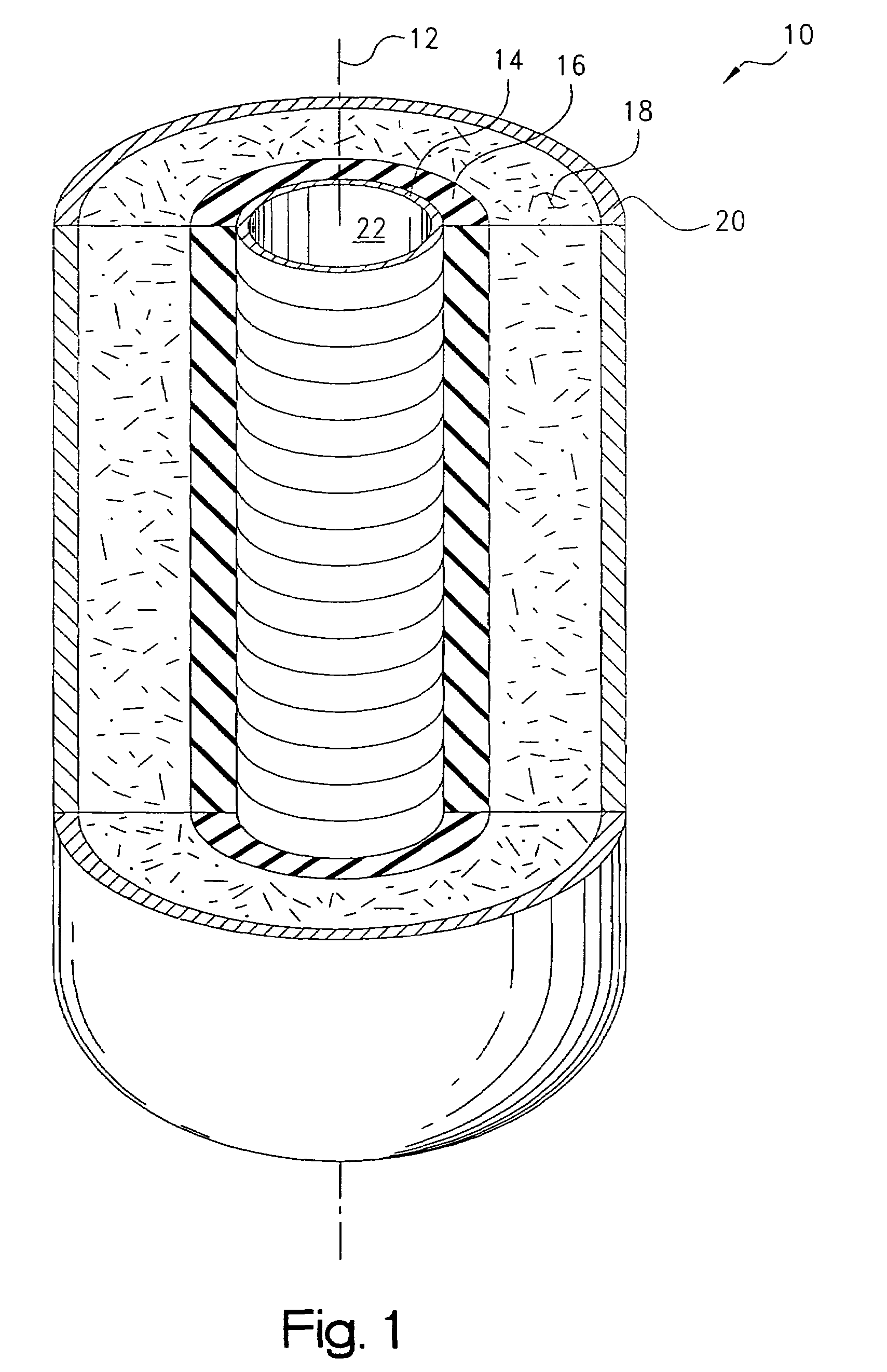
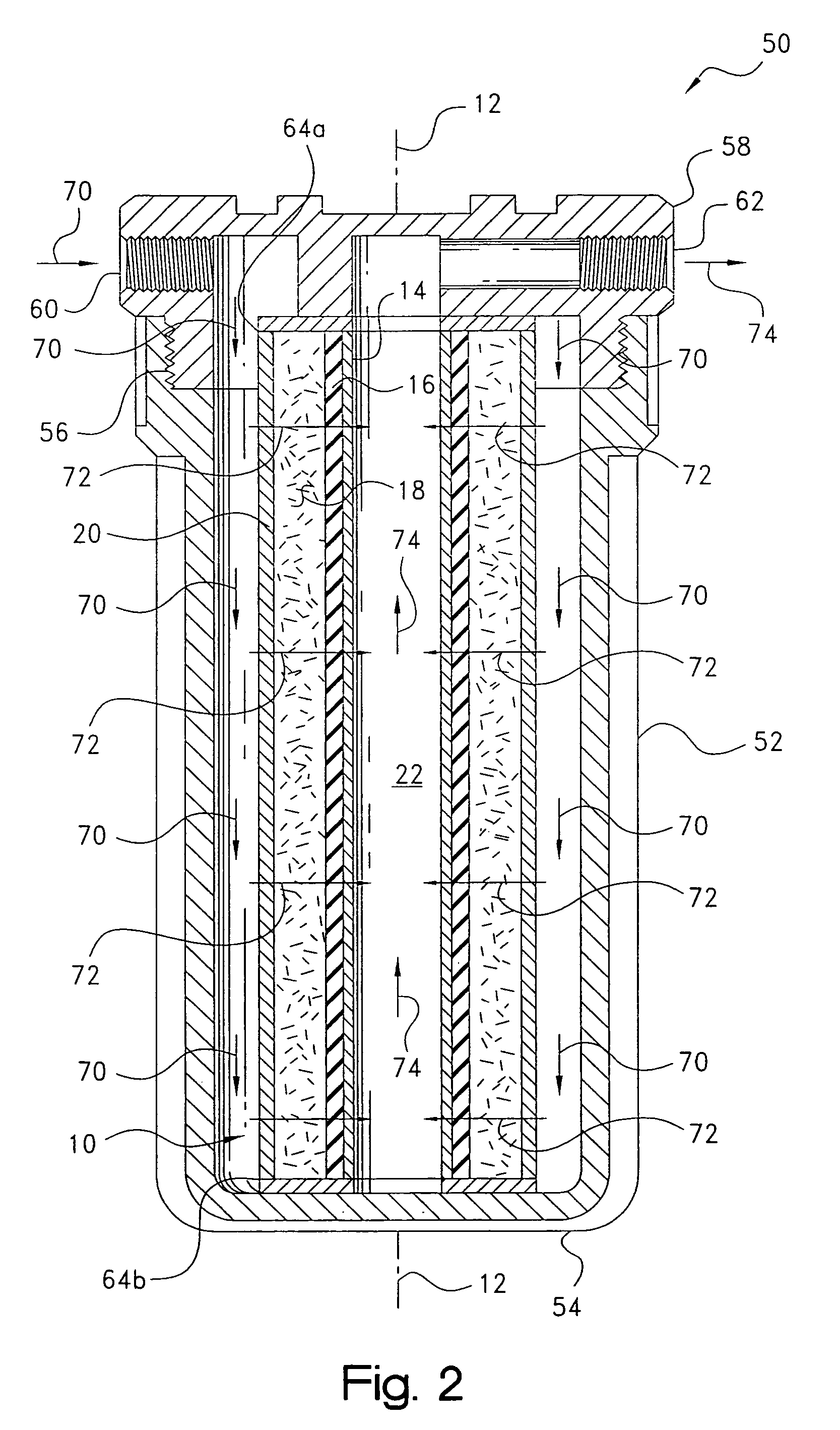
[0013]Certain terminology may be employed in the following description for convenience rather than for any limiting purpose. For example, the terms “forward” and “rearward,”“front” and “rear,”“right” and “left,”“upper” and “lower,”“top” and “bottom,” and “right” and “left” designate directions in the drawings to which reference is made, with the terms “inward,”“inner,”“interior,” or “inboard” and “outward,”“outer,”“exterior,” or “outboard” referring, respectively, to directions toward and away from the center of the referenced element, the terms “radial” or “vertical” and “axial” or “horizontal” referring, respectively, to directions, axes, or planes perpendicular and parallel to the longitudinal central axis of the referenced element, and the terms “upstream” and “downstream” referring, respectively, to fluid state before and after flow through a filter or other element of concern. Terminology of similar import other than the words specifically mentioned above likewise is to be con...


PUM

PropertyMeasurementUnit
Densityaaaaaaaaaa
Shapeaaaaaaaaaa
Oleophilicityaaaaaaaaaa

Abstract

An oil-sorbing filter element for removing oil from an aqueous flow such as the bilge water of a watercraft. The element includes a first stage which is formed of a consolidated permeable mass of a oleophilic polymeric material such as styrenic mid-block copolymer.

Description

CROSS-REFERENCE TO RELATED CASES[0001]The present application claims the benefit of the filing date of U.S. Provisional Application Ser. No. 60 / 454,082; filed Mar. 11, 2003, the disclosure of which is expressly incorporated herein by reference.BACKGROUND OF THE INVENTION[0002]The present invention relates broadly to the removal of oil, fuels, and other hydrocarbons or solvents from water, which may be fresh, salt, brackish, or other, and more particularly to an oil-sorbing filter cartridge or other type element such as for a bilge water treatment system for a watercraft.[0003]Various systems are known for removing at least some of the oil and other hydrocarbons, which often is contained in bilge water before the water is pumped overboard or otherwise discharged. Such systems are described, for example, in commonly-assigned WO 02 / 062445, and in U.S. Pat. Nos. 4,031,839; 4,066,545; 4,058,463; and 6,056,881. Many of these systems utilize a cartridge-type or other filter element having ...

Claims


Application Information

Patent Timeline
IPC IPC(8): B01D15/00B01D17/02B01D39/04B01J20/26C02F1/28C02F1/40
CPCB01D17/0202C02F2201/006C02F1/40C02F1/285B01D17/02
Inventor DENTON, DONALD RHERRICK, DOUGLAS E.LANE, GEARYMOHR, KIRBY S.
Owner PARKER INTANGIBLES LLC
Why Eureka
Try Eureka