
Method and apparatus for endpoint detection using partial least squares

a technology of partial least squares and endpoint detection, applied in the field of endpoint detection, can solve the problems of reduced robustness, single and dual wavelength endpoint detection schemes have found limited use, and poor quality devices are subject to increased risk of failure, so as to improve the detection of feature etch completion

Inactive Publication Date: 2007-11-20
TOKYO ELECTRON LTD
View PDF10 Cites 10 Cited by
  • Summary
  • Abstract
  • Description
  • Claims
  • Application Information

AI Technical Summary

Benefits of technology

The present invention provides an apparatus and method for improved detection of a feature etch completion. The apparatus includes an etching reactor and an end-point detector for detecting an endpoint of the etch process. The method includes determining a correlation matrix by recording first measured data regarding a first etch process over time and analyzing it to refine the data. The refined data is then used to determine if an endpoint of the etch process has been achieved. The technical effect of this invention is to provide a more accurate and reliable method for detecting the completion of a feature etch process.

Problems solved by technology

If the etch process endpoint is improperly detected, then severe under-cutting of the feature may occur due to over-etching or partially complete features may result due to underetching.
As a result, poor endpoint detection could lead to devices of poor quality that are subject to increased risk of failure.
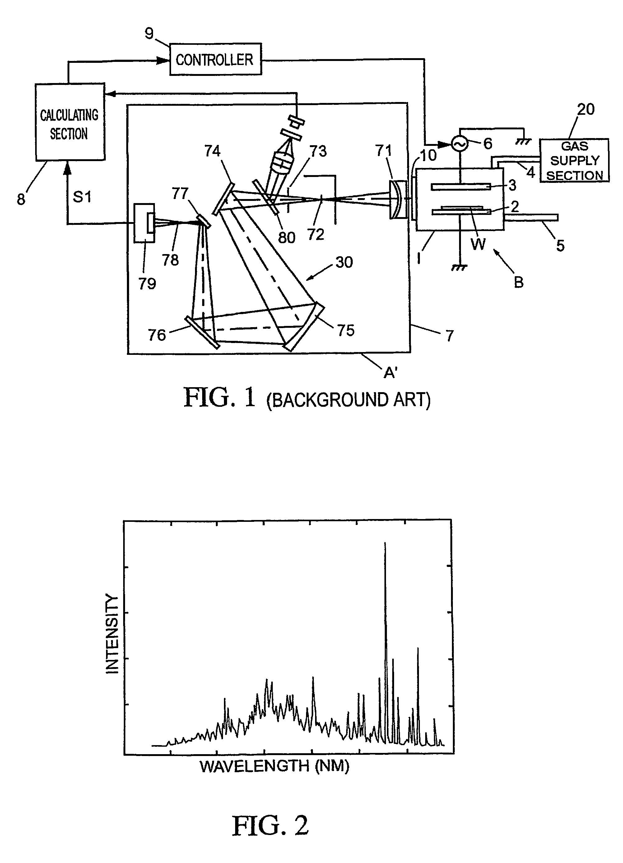
However, as the IC device sizes have decreased, and the exposed open areas have correspondingly decreased, single and dual wavelength endpoint detection schemes have found limited use due to their reduced robustness for extracting a low signal-to-noise (S / N) endpoint signal from the process.
However, a shortcoming of the use of PCA for multivariate analysis of optical emission data includes the mathematical rigor and complexity such an analysis entails, and, more importantly, the lack of use of physical criteria associated with the etch process to extract a reduced set of data including the endpoint signal(s).

Method used


Image

  • Method and apparatus for endpoint detection using partial least squares
  • Method and apparatus for endpoint detection using partial least squares
  • Method and apparatus for endpoint detection using partial least squares

Examples


Embodiment Construction

[0033]As stated above, the inventors have identified problems with conventional processing reactors and methods of using those reactors that are solved by the present invention. Therefore, the present invention provides an improved apparatus and method for endpoint detection which overcomes the shortcomings identified with regard to the conventional processing reactors.

[0034]The inventors recognized that it is difficult to accurately detect the endpoint for the etch process of a small open area substrate. As the device sizes shrink, the open area shrinks and consequently the endpoint signal and the signal-to-noise ratio are reduced. What is needed is a simplified multivariate analysis approach for extracting endpoint signal(s) utilizing known physical criteria set by the etch process.

[0035]Additionally, the inventors have recognized that it is difficult to repeatedly detect the endpoint for an etch process from wafer-to-wafer. The endpoint detection algorithm must be robust enough t...


PUM

PropertyMeasurementUnit
wavelengthsaaaaaaaaaa
thresholdaaaaaaaaaa

Abstract

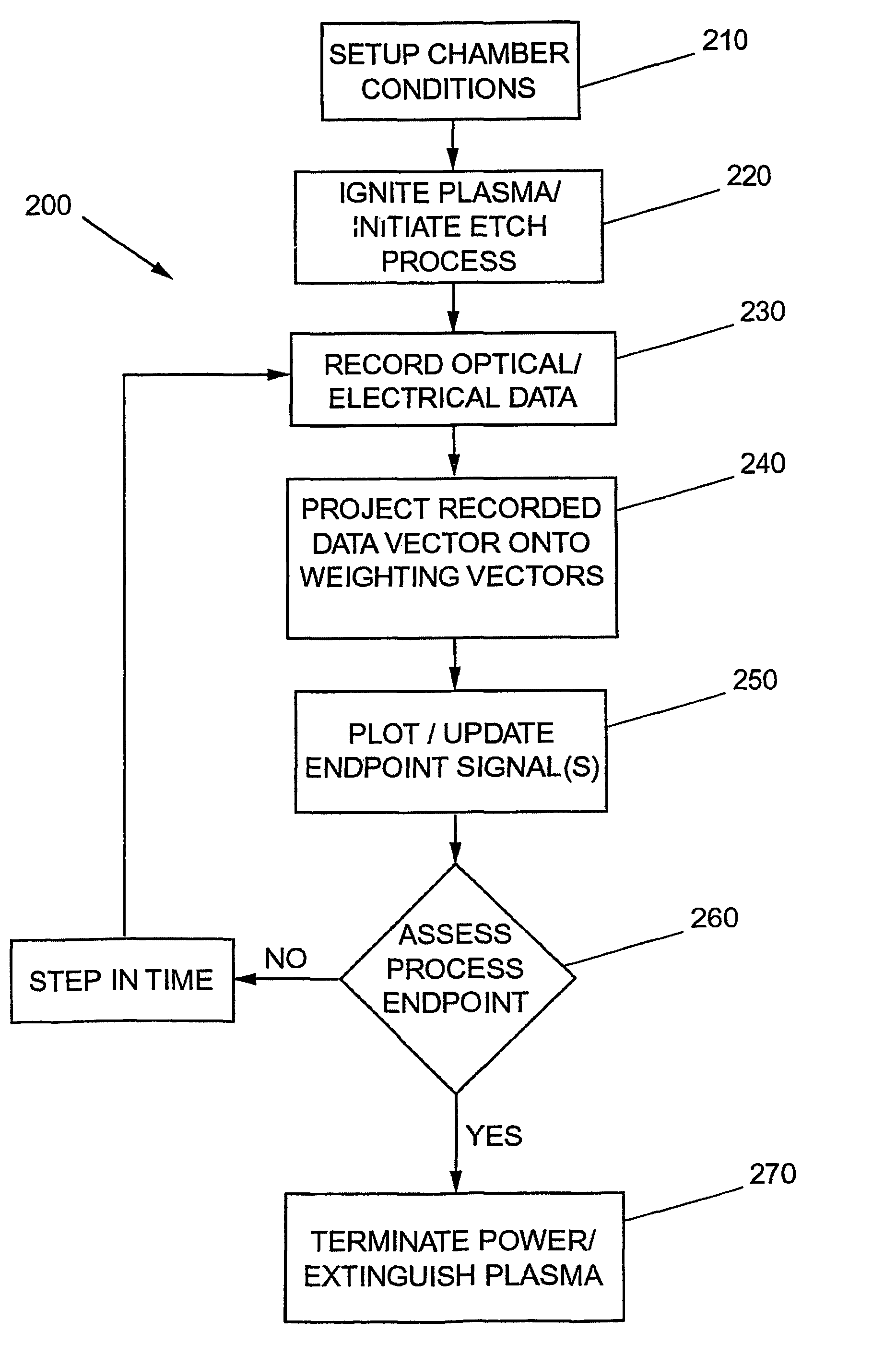
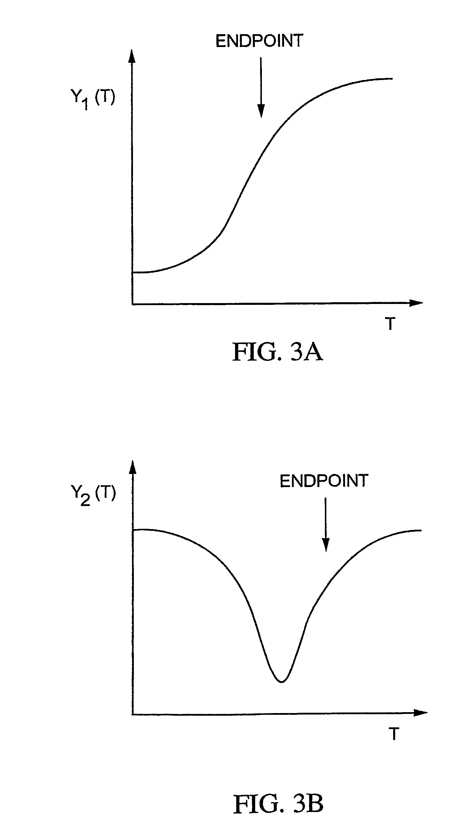
An apparatus and method for detection of a feature etch completion within an etching reactor. The method includes determining a correlation matrix by recording first measured data regarding a first etch process over successive time intervals to form a first recorded data matrix, assembling a first endpoint signal matrix using target endpoint data for a specific etch process, performing a partial least squares analysis on the recorded data matrix and the first endpoint signal matrix to refine the recorded data matrix, and computing a correlation matrix based upon the refined recorded data matrix and the first endpoint signal matrix. The method further includes performing a second etch process to form a second recorded data matrix. The correlation matrix and the second recorded data matrix are analyzed to determine whether an endpoint of the second etch process has been achieved.

Description

CROSS-REFERENCE TO RELATED APPLICATIONS[0001]This application claims priority to International Application No. PCT / US02 / 09073, filed Mar. 25, 2002; which claims priority to U.S. Provisional Application Ser. No. 60 / 277,981, filed Mar. 23, 2001. The entire contents of these applications is incorporated herein by reference.BACKGROUND OF THE INVENTION[0002]1. Field of the Invention[0003]The present invention relates generally to endpoint detection during semiconductor manufacturing.[0004]2. Discussion of the Background[0005]The inventors have identified problems with conventional processing reactors and methods of using those reactors that are solved by the present invention.[0006]Typically, during semiconductor processing, a (dry) plasma etch process is utilized to remove or etch material along fine lines or within vias or contacts patterned on a silicon substrate. The plasma etch process generally involves positioning a semiconductor substrate with an overlying patterned, protective l...

Claims


Application Information

Patent Timeline
Patent Type & Authority Patents(United States)
IPC IPC(8): H01L21/306H01L21/3065H01J37/32H01L21/66
CPCH01J37/32935H01J37/32963H01L22/20H01L2924/0002H01L2924/00G01J3/457
Inventor FATKE, DAVIDYUE, HONGYU
Owner TOKYO ELECTRON LTD
Learn More