Tunable multi-band receiver by on-chip selectable filtering

Inactive Publication Date: 2007-11-20
SHEN REALTY
View PDF8 Cites 16 Cited by
  • Summary
  • Abstract
  • Description
  • Claims
  • Application Information

AI Technical Summary

Benefits of technology

[0014]Accordingly, it is a primary object of the present invention to provide a multiple frequency band radio receiver design, which has increased integration and decreased power consumption without the operational problems associated with previous receiver designs. It is a further object of the invention to provide an equivalent performance to the traditional multi-band superheterodyne receiver of FIG. 1.
[0015]The present invention achieves the ab

Problems solved by technology

Moreover, the necessity for mixer and local oscillator circuits operating at high frequencies contributes greatly to the power consumption and general complexity of the superheterodyne receiver.
In particular, the high-frequency analog mixers require a large amount of power to maintain linear operation.
Although many variations of the superheterodyne design exist, they all share the limitations of the particular design just described.
The direct-conversion design, however, has several problems, some of which are quite serious.
Moreover, this design requires the use of high-frequency mixer and LO circuits that require large amounts of power.
This DC offset can be much greater than the desired zero-IF signal, making signal reception difficult.
This can b

Method used


Image

  • Tunable multi-band receiver by on-chip selectable filtering
  • Tunable multi-band receiver by on-chip selectable filtering
  • Tunable multi-band receiver by on-chip selectable filtering

Examples


Example

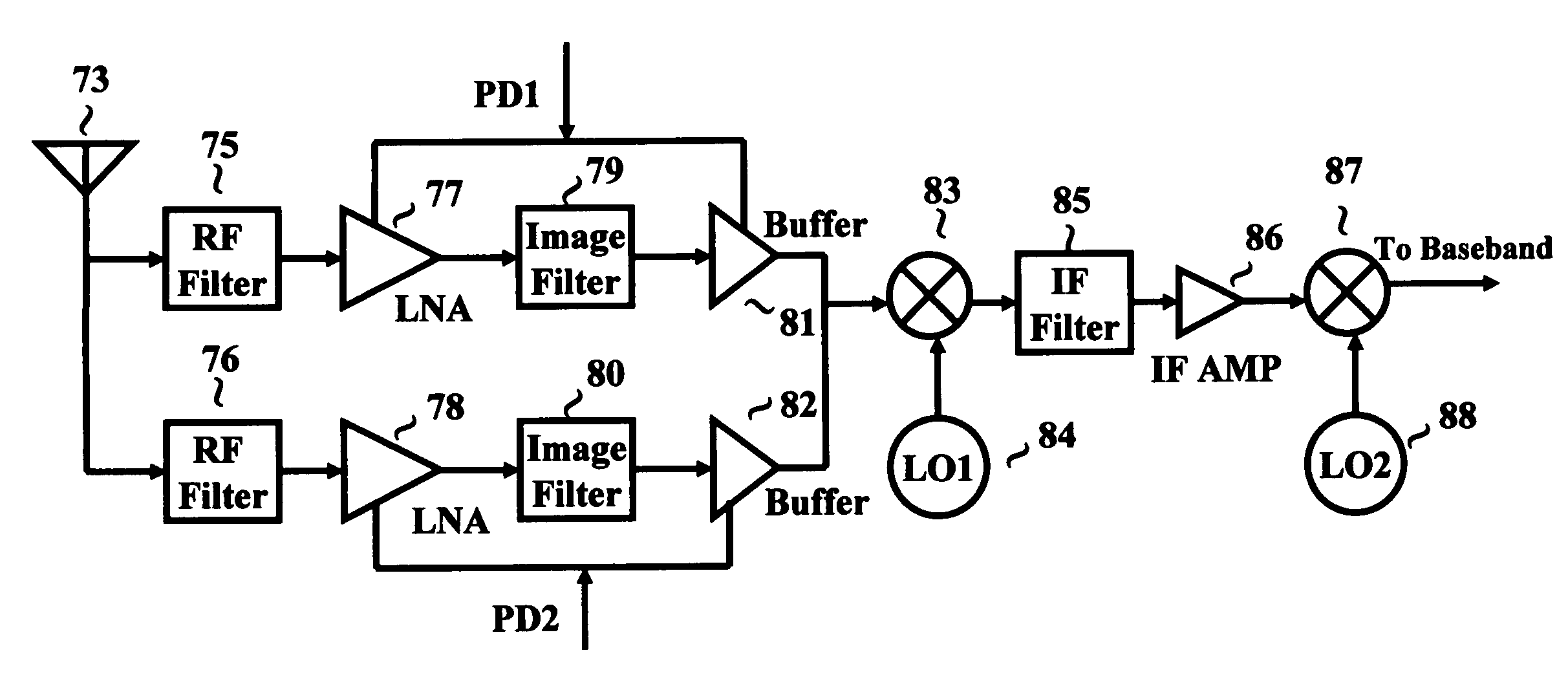
[0020]FIG. 3 is a block diagram of a dual-band RF communications receiver constructed in accordance with the principles of the present invention. It includes an antenna 73 for coupling a RF signal into the input of a bandpass RF filter, 75 and 76, for each frequency band. The output of the analog bandpass RF filters, 75 and 76, connects to the input of an LNA, 77 and 78, for each frequency band and whose output couples to the input of an image filter, 79 and 80, for each frequency band. The architecture differs from the tradition receiver at this point. Two buffers, 81 and 82, have outputs that are combined together. Each LNA, 77 and 78, and buffer, 81 and 82, have power down controls, PD1 and PD2, which enable one frequency band to be selected versus the other frequency band. The method of powering down the circuits enables high isolation that is not achievable in other switchable filters in the prior art U.S. Pat. Nos. 6,064,866[1] and 4,972,509[2]. The combined output is then fed...


PUM


Abstract

A multiple frequency RF communications receiver is disclosed which permits greater integration on standard silicon chips and consumes less power than previous receivers. A new method for selecting the various frequency bands with a high amount of isolation and low power consumption is described. Compared to previous receiver implementations, there is no loss of selectivity in the receiver.

Description

[0001]This application claims benefit of application Ser. No. 60 / 431,977 filed Dec. 10, 2002.REFERENCES[0002]U.S. Pat. No. 6,064,866, May 16, 2000, Lange.[0003]U.S. Pat. No. 4,972,509, Nov. 20, 1990, Maejima.BACKGROUND—TECHNICAL FIELD OF INVENTION[0004]The present invention relates to radio receivers and methods for the reception of RF (radio frequency) communications signals in multiple frequency bands. In particular, it relates to integrated circuit based radio receivers using programmable on-chip tuning.BACKGROUND OF THE INVENTION AND DISCUSSION OF PRIOR ART[0005]At the present time, the vast majority of RF communications receivers are of the superheterodyne type. This type of receiver uses one or more IF (intermediate frequency) stages for filtering and amplifying signals at a fixed frequency within an IF chain. This radio architecture has the advantage that fixed filters may be used in the LO chain. In order for the receiver to be useable over multiple bands, its typical archit...

Claims


Application Information

Patent Timeline
IPC IPC(8): H04B1/18H04B1/28H04B1/30H04B1/40
CPCH04B1/005H04B1/406H04B1/30H04B1/28
Inventor SHEN, DAVID H.SHEN, ANN P.
Owner SHEN REALTY
Why Eureka
Try Eureka