
Front opening shipping box and method of operating the same

a shipping box and front opening technology, applied in the direction of transportation and packaging, packaging type, container preventing decay, etc., can solve the problems of wasting a lot of money, not providing special treatment, and increasing the precision of each processing step

Active Publication Date: 2007-11-27
UNITED MICROELECTRONICS CORP
View PDF9 Cites 8 Cited by
  • Summary
  • Abstract
  • Description
  • Claims
  • Application Information

AI Technical Summary

Benefits of technology

[0008]Accordingly, at least one objective of the present invention is to provide a front opening shipping box (FOSB) that can avoid the problem of generating particle contaminants and / or damaging the wafers in the conventional method of injecting nitrogen into the FOSB through an air hole.
[0009]At least another objective of the present invention is to provide another type of front opening shipping box (FOSB) that can avoid the problem of generating particle contaminants and / or damaging the wafers in the conventional method of injecting nitrogen into the FOSB through an air hole.
[0010]At least another objective of the present invention is to provide a method of operating a front opening shipping box (FOSB) that can pump out and inject air into the box simultaneously and effectively to reduce the oxygen and moisture content inside the box. Furthermore, the method can prevent the generation of particle contaminants inside the box and reduce possible damage to the wafers.
[0011]At least yet another objective of the present invention is to provide another method of operating a front opening shipping box (FOSB) that can pump air out and inject air into the box simultaneously and effectively to reduce the oxygen and moisture content inside the box. Furthermore, the method can prevent the generation of particle contaminants inside the box and reduce possible damage to the wafers.
[0028]The FOSB and method of operating the same in the present invention utilizes an air extraction and a gas injection pipe elements including the air extraction pipeline and the gas inlet pipeline or the concentric sleeve pipeline to draw air out of the box and inject gas back in simultaneously. In this way, the difference in pressure between the outside and the inside of the FOSB is almost equalized. Without the need to create a partial vacuum by pumping air out before injecting gas in as in the conventional method, problems including particle contaminants and / or damage of the wafers, and / or the inability of injecting gas into the container body can be avoided. Furthermore, the FOSB and the method of operating the FOSB according to the present invention can significantly reduce the oxygen and moisture content inside the box. In other words, the change of having to throw away the wafers due to oxidation and corrosion inside the box is substantially reduced.

Problems solved by technology

However, as the integration of semiconductor devices in integrated circuits continues to increase day by day, the precision of each processing step has become increasingly critical.
Therefore, if a minor error or contamination in the process of transporting wafers occurs, the wafers may be damaged and need to be thrown away or scrapped into pieces that a lot of money is wasted.
In particular, special treatment is often not provided to a front opening shipping box (FOSB) before transporting it outside of a processing plant.
Thus, the oxygen and moisture inside the FOSB often react with the wafers to cause wafer damage.
However, injecting nitrogen into the FOSB directly through the air hole is infeasible because the box is full of air.
The drawback of this method is that the rapid intrusion of nitrogen into the box will lead to the formation of particle contaminants and / or damage of the wafers due to the substantial pressure difference between the inside and the outside of the box.
As a result, some of the wafers may have to be scrapped resulting in an increase of the production cost.

Method used


Image

  • Front opening shipping box and method of operating the same
  • Front opening shipping box and method of operating the same
  • Front opening shipping box and method of operating the same

Examples


Embodiment Construction

[0034]Reference will be made in detail to the present preferred embodiments of the invention, examples of which are illustrated in the accompanying drawings. Wherever possible, the same reference numbers are used in the drawings and the description to refer to the same or like parts.

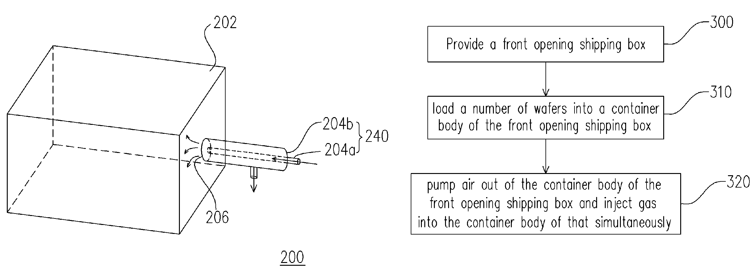
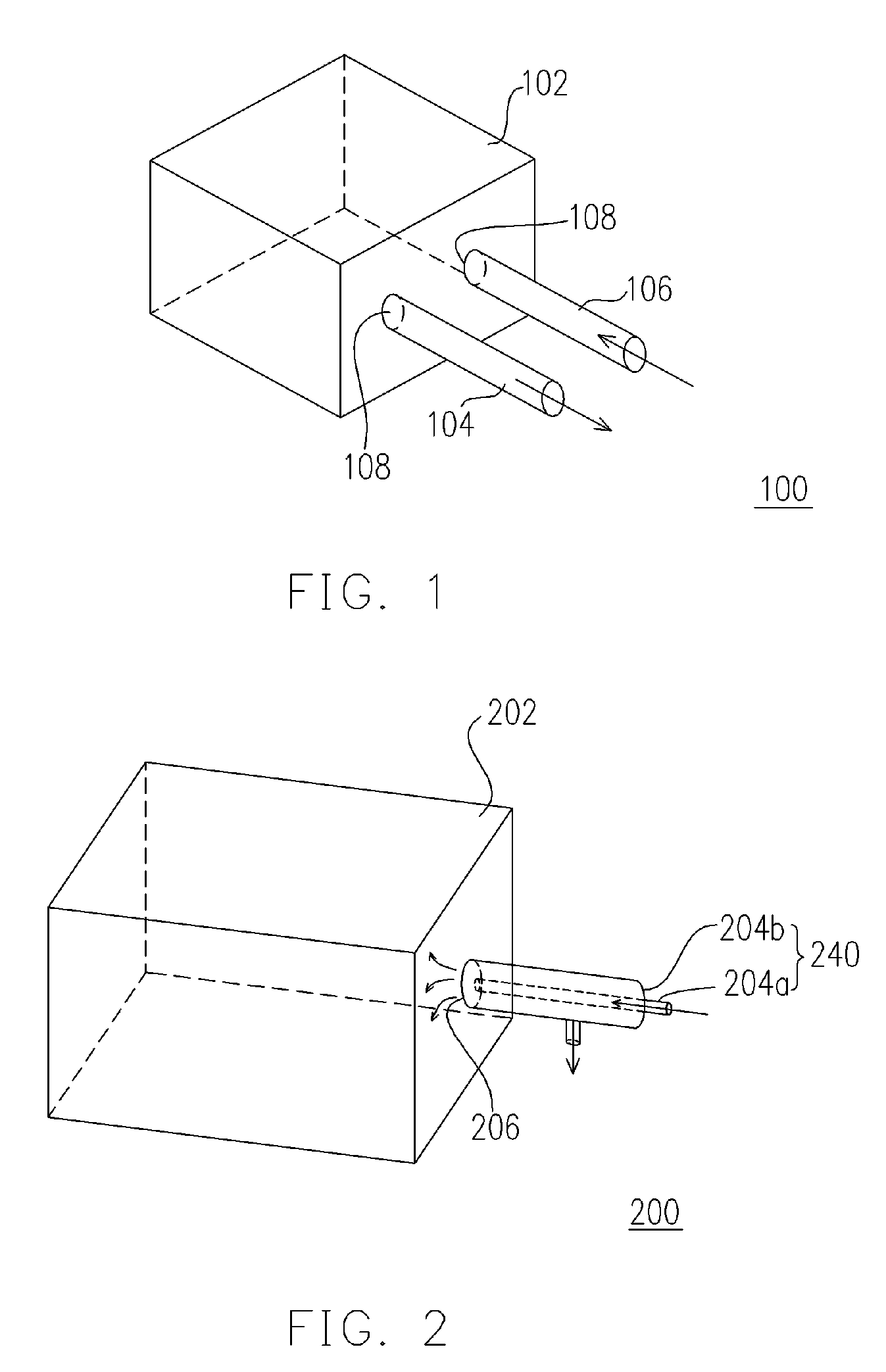
[0035]The front opening shipping box (FOSB) in the present invention differs from a front opening unified pod (FOUP). The FOSB is mainly used as a carrier for transporting wafers from one plant facility to another. FIG. 1 is a perspective view of a front opening shipping box according to one embodiment of the present invention. FIG. 2 is a perspective view of a front opening shipping box according to another embodiment of the present invention.

[0036]As shown in FIG. 1, the front opening shipping box (FOSB) 100 in the present invention includes at least a container body 102, an air extraction pipeline 104 and a gas inlet pipeline 106. The container body 102 has two openings 108. In the present embodiment,...


PUM

PropertyMeasurementUnit
timeaaaaaaaaaa
distanceaaaaaaaaaa
gas flow rateaaaaaaaaaa

Abstract

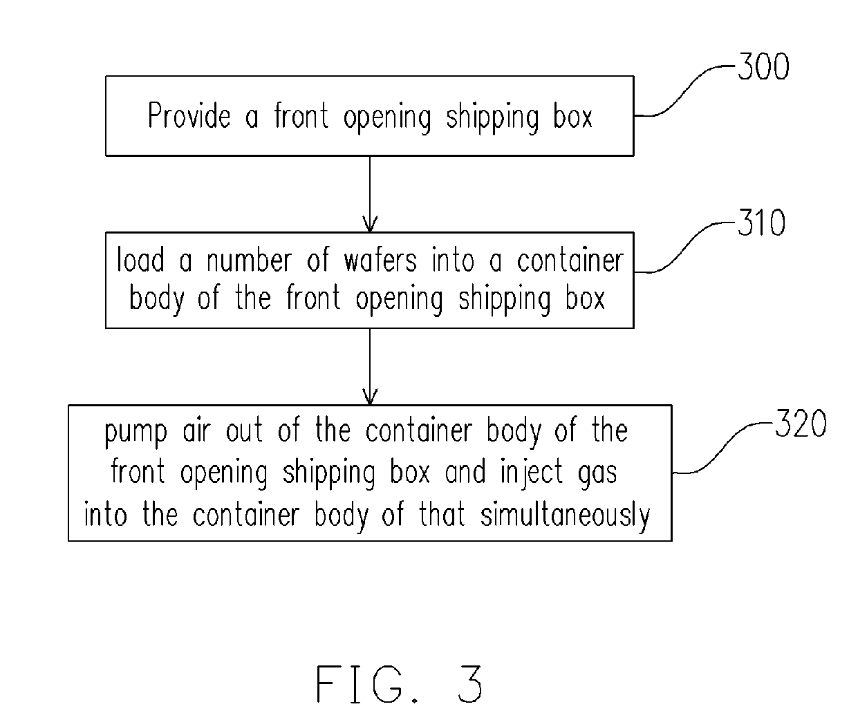
A method of operating a front opening shipping box is provided. The operating method comprises providing a front opening shipping box. The front opening shipping box includes at least a container body, at least an air extraction pipeline and at least a gas inlet pipeline. The container body has at least two openings. The air extraction pipeline is disposed on the surface of the container body and linked to the container body through one of the two openings. The gas inlet pipeline is also disposed on the surface of the container body and linked to the container body through the outer opening. Then, a number of wafers are loaded inside the container body. Next, through the air extraction pipeline and the gas inlet pipeline, air is pumped out from the inside of the container box while the gas is injected into the container body simultaneously.

Description

BACKGROUND OF THE INVENTIONDESCRIPTION[0001]1. Field of the Invention[0002]The present invention relates to a semiconductor apparatus and operating method thereof. More particularly, the present invention relates to a front opening shipping box and method of operating the same.[0003]2. Description of the Related Art[0004]At present, in the semiconductor manufacturing industry, front opening unified pod (FOUP) and front opening shipping box (FOSB) are commonly used as a receptacle for carrying and transporting wafers. The front opening unified pod (FOUP) is mainly used inside a wafer fabrication plant for carrying, transporting and protecting wafers between stations or between processes. The method of operation the FOUP includes putting the wafers inside the FOUP to prevent any dust particles in the atmosphere from contaminating the wafers. When there is a need to transfer the wafers to a particular piece of processing equipment, the lid of the FOUP is opened and a robotic arm is use...

Claims


Application Information

Patent Timeline
Patent Type & Authority Patents(United States)
IPC IPC(8): B65B31/00B65D81/20
CPCH01L21/67393H01L21/67017
Inventor HORNG, JIAN-PINGLIN, CHENG-CHIENLU, WEN-ANLIN, YU-MEIWENG, WU-FU
Owner UNITED MICROELECTRONICS CORP
Learn More