Eureka AIR delivers breakthrough ideas for toughest innovation challenges, trusted by R&D personnel around the world.

Method and apparatus for real time monitoring of an electric furnace heating coil

a technology of real-time monitoring and heating coil, which is applied in the field of electric furnaces, can solve the problems of reducing furnace temperature, adverse effects on the thickness of deposited oxide, and affecting the effect of furnace heating coil thickness, and achieves the effect of simple construction and easy retrofitting

Active Publication Date: 2007-11-27
TAIWAN SEMICON MFG CO LTD
View PDF8 Cites 3 Cited by
  • Summary
  • Abstract
  • Description
  • Claims
  • Application Information

AI Technical Summary

Benefits of technology

[0010]A still further object of the invention is to provide a method and apparatus as described above which allows real-time monitoring of the heating coil in a manner that does not affect normal operation of temperature control equipment or require substantial modification of existing equipment.
[0011]Another object of the invention is to provide heating coil monitoring apparatus as mentioned above which is simple in construction and is easily retrofitted to existing furnace installations.

Problems solved by technology

Many of such processes require relatively close temperature control, otherwise the results are adversely effected.
For example, when oxides are being deposited on a wafer, if there is a dramatic shift in temperature during processing, the thickness of the deposited oxide may be adversely affected, e.g. the deposited thickness is below the specified requirements.
Unexpected temperature variations in furnaces used to conduct wafer processing may result from a variety of causes.
In many cases, one or more electric heating elements may fail or may operate intermittently, which in turn reduces furnace temperature.
These failures are sometimes due to deterioration of heating coils due to age, which results in the coil experiencing an open circuit at the location where the coil has failed.
Unfortunately, since the data log was reviewed only after processing cycles were completed, the entire batch of wafers often had to be scrapped since corrective action could not be taken until the process was completed.

Method used


Image

  • Method and apparatus for real time monitoring of an electric furnace heating coil
  • Method and apparatus for real time monitoring of an electric furnace heating coil

Examples


Embodiment Construction

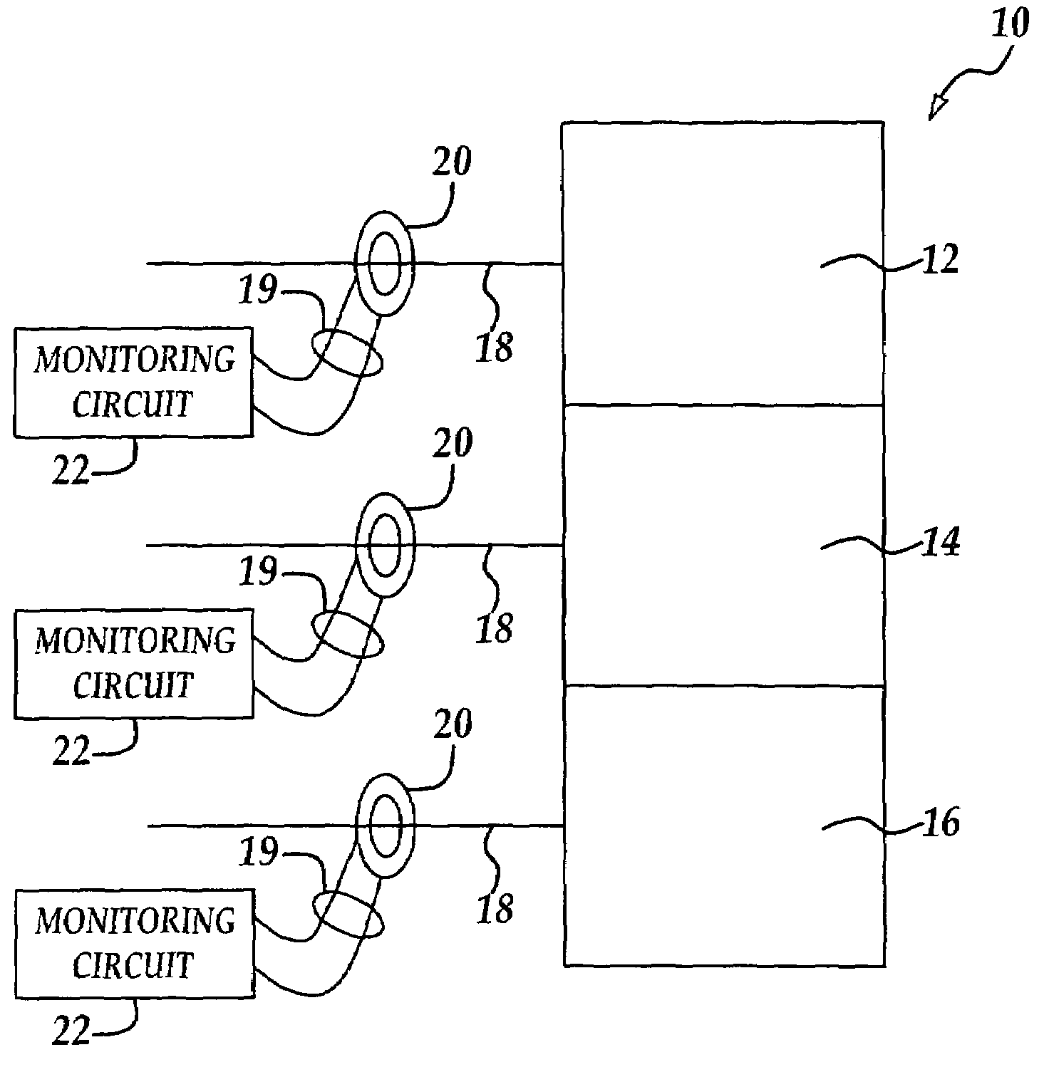
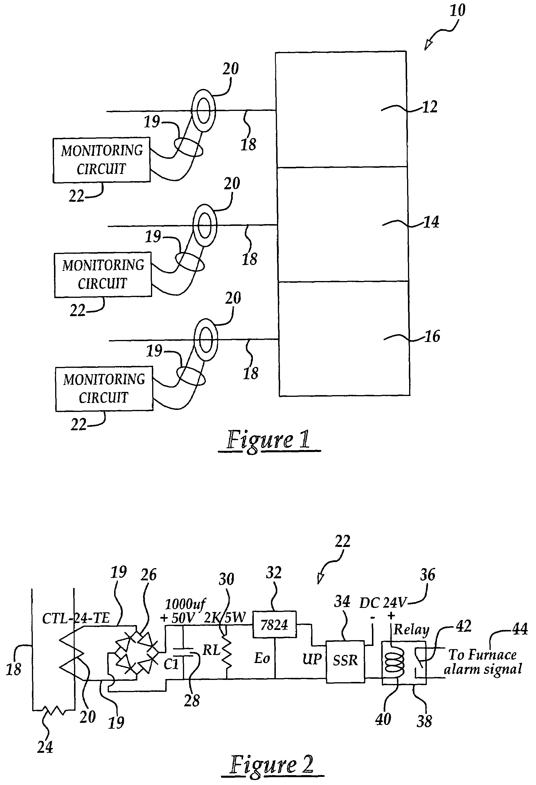
[0016]Referring first to FIG. 1, a furnace generally indicated by the numeral 10 of the so-called vertically oriented type includes a plurality of separately controllable furnace zones 12, 14, 16 which may have the same, or different operating temperatures. Each of the furnace zones 12-16 is heated by a series of electrical heating elements or coils (not shown) which are connected with and receive power from an electrical power line 18. The furnace 10 is controlled by an appropriate controller (not shown) such as a conventional proportional-integral derivative (PID) temperature controller having, for example, 256 resolutions and a range of zero to 100 percent of power output by controlling the trigger angle of a high powered type SCR. The furnace 10 is typically driven in a low voltage and high current mode. The magnitude of the AC current flowing through the power line 18 is related to the temperature within the corresponding furnace zones 12-16.

[0017]In accordance with the present...


PUM


Abstract

Heating coils used in an electric furnace used to process semiconductor wafers are monitored on a real time basis by sensing the AC current in a power line delivering electrical power to the furnace. The AC current is sensed by a coil positioned around and magnetically coupled with the power line. The sensed AC current induces an AC voltage in the coil which is converted by an electrical circuit into a DC voltage. The DC voltage is used to control a solid state relay that generates an alarm signal when the value of the DC voltage is less than a preselected value indicating that an open circuit is present in the heating coil.

Description

TECHNICAL FIELD[0001]The present invention broadly relates to electric furnaces used to process semiconductor wafers, and deals more particularly with a method and apparatus for monitoring heating coils used in such furnaces, on a real time basis.BACKGROUND ART[0002]Electrically powered furnaces are used extensively in various processes for producing integrated circuits on semiconductor wafers. In some cases, these furnaces are used to cure wafers following a process step, while in other cases the furnaces are used to heat the wafers to a particular temperature during a process, such as oxidation or re-flow conducted on the wafer surface. Many of such processes require relatively close temperature control, otherwise the results are adversely effected. For example, when oxides are being deposited on a wafer, if there is a dramatic shift in temperature during processing, the thickness of the deposited oxide may be adversely affected, e.g. the deposited thickness is below the specified...

Claims


Application Information

Patent Timeline
Patent Type & Authority Patents(United States)
IPC IPC(8): G08B21/00
CPCG01R31/42
Inventor PAI, JIUN-RONG
Owner TAIWAN SEMICON MFG CO LTD
Why Eureka
Eureka Blog
Learn More