Ultrasonic diagnostic apparatus and image processing apparatus

a diagnostic apparatus and ultrasonic technology, applied in the field of ultrasonic imaging, can solve the problems of reducing the signal strength of the scan surface and the difficulty of extracting micro-vascular branches

Active Publication Date: 2007-12-04
TOSHIBA MEDICAL SYST CORP
View PDF18 Cites 11 Cited by
  • Summary
  • Abstract
  • Description
  • Claims
  • Application Information

AI Technical Summary

Benefits of technology

[0009]The invention was devised in view of the foregoing problems, and therefore has an object to provide an ultrasonic diagnostic apparatus and an image processing apparatus capable of extracting diagnostic information at the level of micro-vascular branches rapidly in an effective manner.

Problems solved by technology

Bubbles, being a delicate material by nature, rupture upon ultrasonic irradiation, even at the ordinary diagnostic level, due to the mechanical function, which results in a decrease in signal strength from the scan surface.
Problems with these images are that it is difficult to extract micro-vascular branches on the former vascular image, whereas in the latter, although signals from micro vessels are detected, the vascular branches are not extracted due to the limit of spatial resolution and merely an increase in luminance can be confirmed as a domain.

Method used


Image

  • Ultrasonic diagnostic apparatus and image processing apparatus
  • Ultrasonic diagnostic apparatus and image processing apparatus
  • Ultrasonic diagnostic apparatus and image processing apparatus

Examples


first embodiment

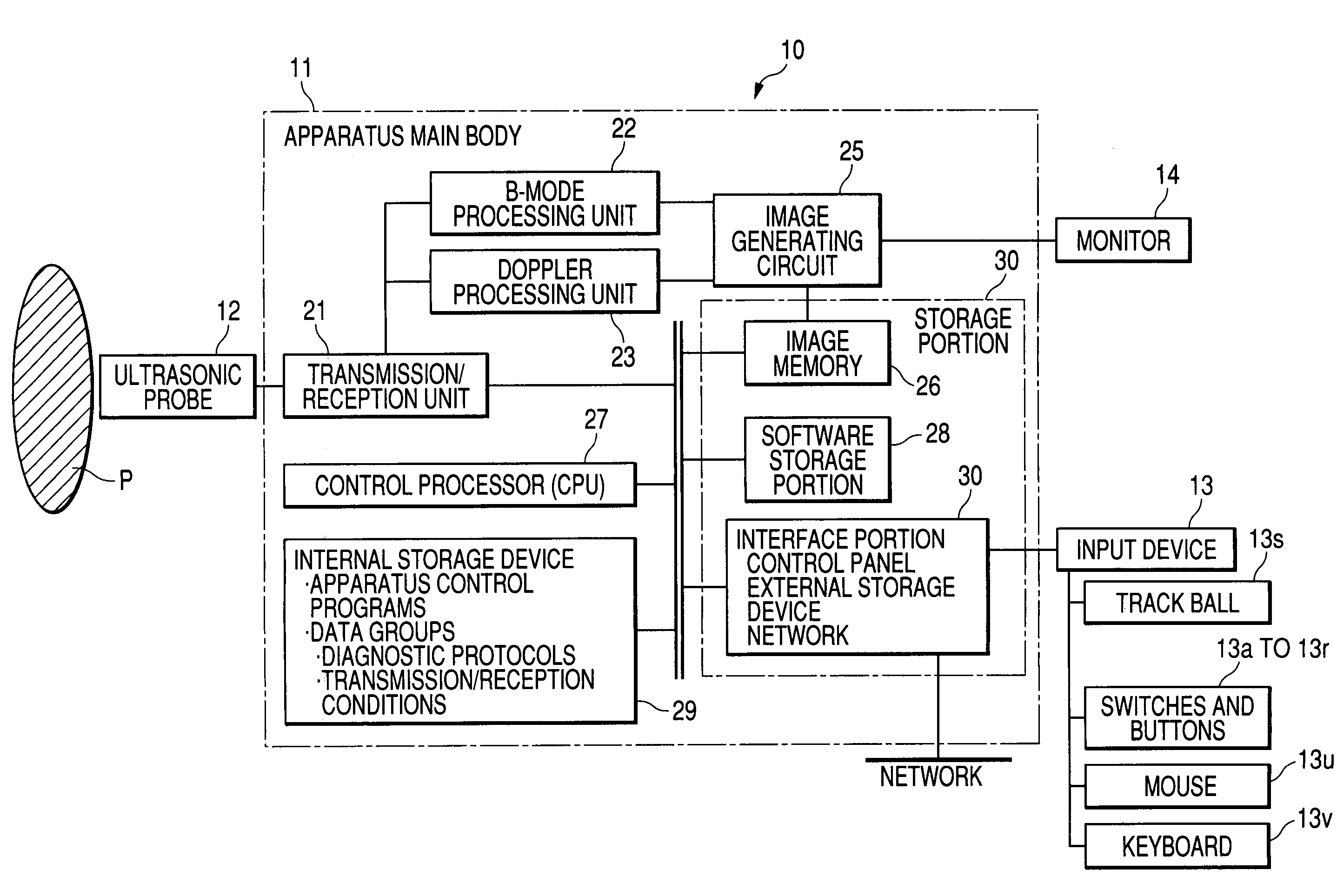
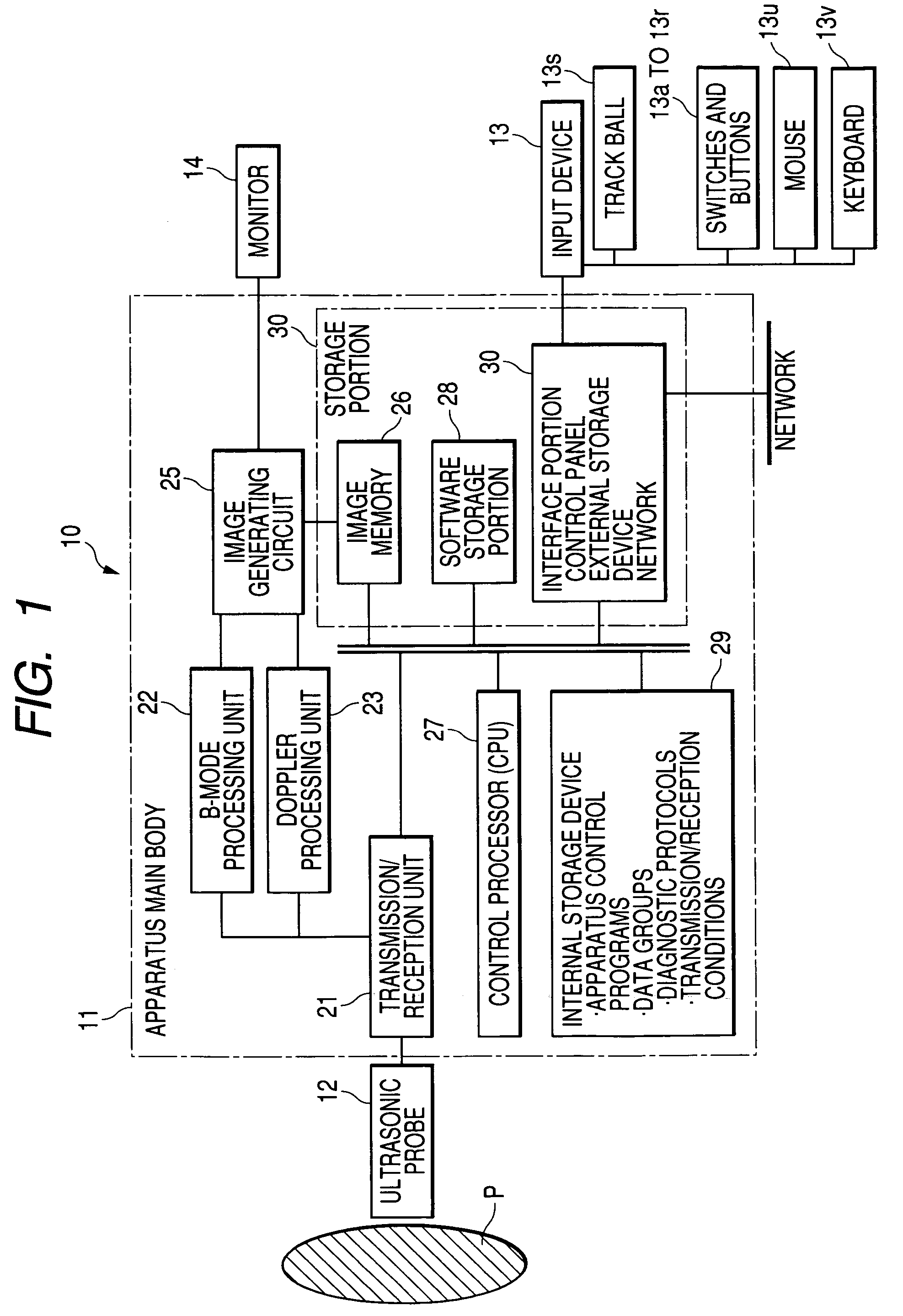
[0033]FIG. 1 is a block diagram showing the configuration of an ultrasonic diagnostic apparatus 10 of this embodiment. As is shown in the drawing, the ultrasonic diagnostic apparatus 10 includes an ultrasonic probe 12, an input device 13, a monitor 14, a transmission / reception unit 21, a B-mode processing unit 22, a Doppler processing unit 23, an image generating circuit 25, an image memory 26, a control processor 27, a software storage portion 28, an internal storage device 29, and an interface portion 30. The ultrasonic transmission / reception unit 21 and the like built into the apparatus main body 11 may be in the form of hardware, such as integrated circuits, or they may be in the form of softwarily modularized software programs. The following description will describe functions of the components individually.

[0034]The ultrasonic probe 12 includes: plural piezoelectric transducers that generate ultrasonic waves according to a driving signal from the ultrasonic transmission / recept...

second embodiment

[0118]A second embodiment of the invention will now be described. This embodiment is to perform the first or second image generating and displaying method in the middle of or after the imaging.

[0119]As has been described, the ultrasonic diagnostic image obtained and observed in real time with the apparatus is also stored in the image memory 26. Hence, when the operator has observed images for a certain time, he generally stops the ultrasound scans through an input from a freeze button on the control panel, so that a series of tomographic images in the image memory 26 are played back. These images can be displayed either like a still image or a moving picture. Also, as is shown in FIG. 18, the operator is able to control the playback, stop, fast forwarding, backward feeding, etc. at arbitrary timing by means of playback buttons 13r and the track ball 13s provided to the input device 13.

[0120]In addition, as is shown in FIG. 18, in the case of the apparatus 10 of this embodiment, the ...


PUM


Abstract

An ultrasonic diagnostic apparatus that performs high acoustic pressure and low acoustic pressure ultrasonic transmissions by switching at predetermined timing in the enhanced ultrasonography, and displays concurrently a replenishment image obtained through the low acoustic pressure transmission in real time like a moving picture, and a pre-flash image obtained through the low acoustic pressure transmission immediately before switching to the high acoustic pressure transmission like a still image to allow the operator to understand the structure at the level of capillaries. It is also possible to display a selected image obtained through the low acoustic pressure transmission at an arbitrary timing instead of the pre-flash image.

Description

CROSS-REFERENCE TO RELATED APPLICATIONS[0001]This application is based upon and claims the benefit of priority from prior Japanese Patent Application No. 2003-124168, filed Apr. 28, 2003, the entire contents of which are incorporated herein by reference.BACKGROUND OF THE INVENTION[0002]1. Field of the Invention[0003]The present invention is in the field of the enhanced ultrasonography using an ultrasound contrast medium, and relates to an ultrasonic diagnostic apparatus and an image processing apparatus capable of presenting, as diagnostic information, a microcirculation at the level of capillaries and the microstructure of a vascular flow relatively fast compared with capillaries.[0004]2. Description of the Related Art[0005]An ultrasonic diagnosis is convenient in that beat pulsations of the heart or motions of a fetus can be obtained as a real-time display through a manipulation as simple as placing an ultrasonic probe to the body surface, and a screening can be performed repetiti...

Claims


Application Information

Patent Timeline
IPC IPC(8): G01N29/07A61B8/00A61B8/06G01S7/52G01S15/89
CPCA61B8/06A61B8/13A61B8/481G01S15/8979G01S7/52041G01S7/52074G01S7/52038
Inventor KAMIYAMA, NAOHISA
Owner TOSHIBA MEDICAL SYST CORP
Why Eureka
Try Eureka