
Hybrid nutating pump

a nut-type pump and hybrid technology, applied in the field of nut-type pumps, can solve the problems of more blow-by leakage over the life of the pump, increased wear, and shorter life, and achieve the effect of eliminating the bearing connection

Inactive Publication Date: 2007-12-04
LYNN WILLIAM HARRY +1
View PDF8 Cites 6 Cited by
  • Summary
  • Abstract
  • Description
  • Claims
  • Application Information

AI Technical Summary

Benefits of technology

This design reduces wear, extends pump life, minimizes leakage, and increases flow efficiency by using split-ring seals and a universal joint to manage side loads, achieving higher performance in a compact space.

Problems solved by technology

Side loading on the pistons results in increased wear, shorter life, and more blow-by leakage over the life of the pump.

Method used


Image

  • Hybrid nutating pump
  • Hybrid nutating pump

Examples


Embodiment Construction

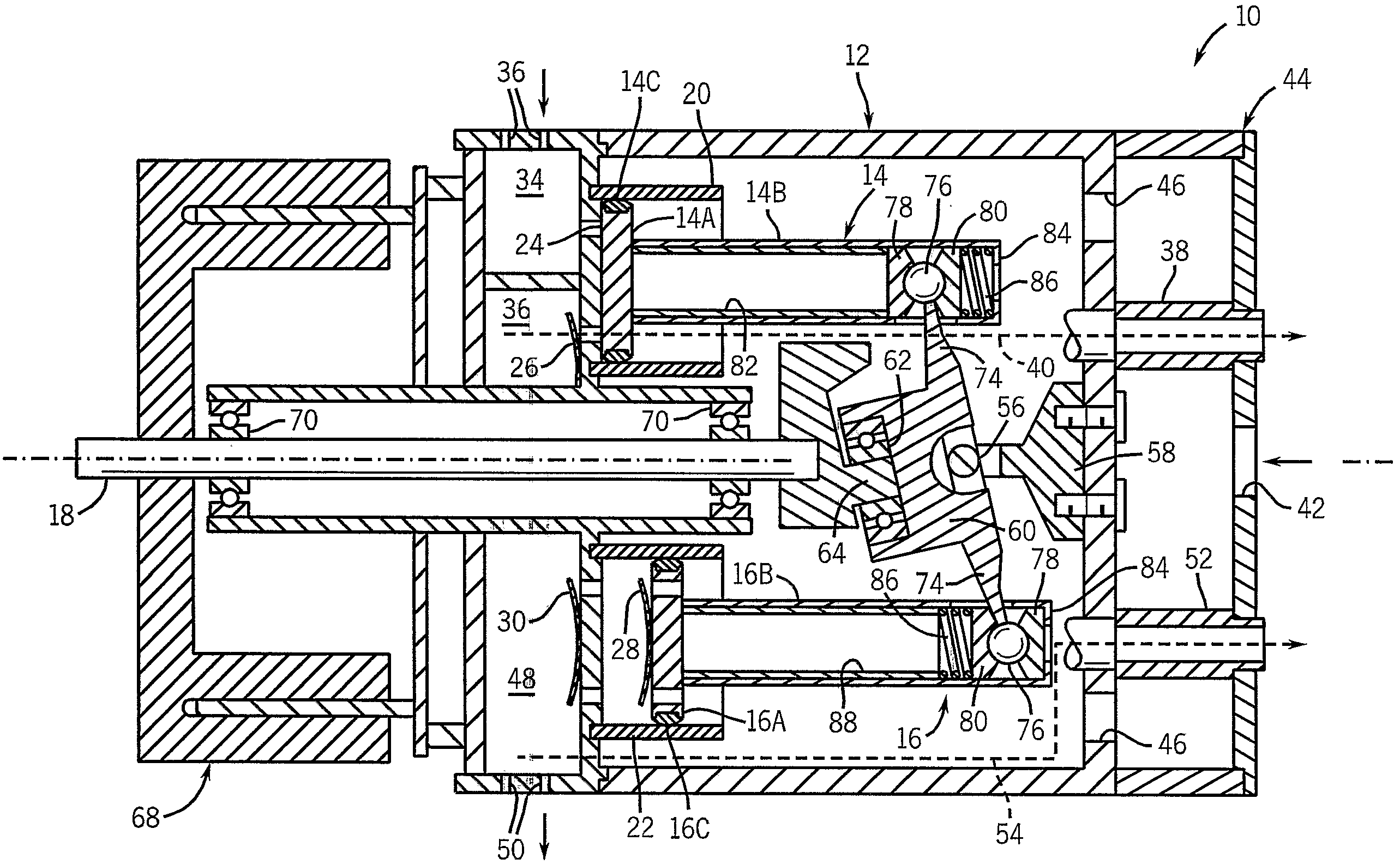
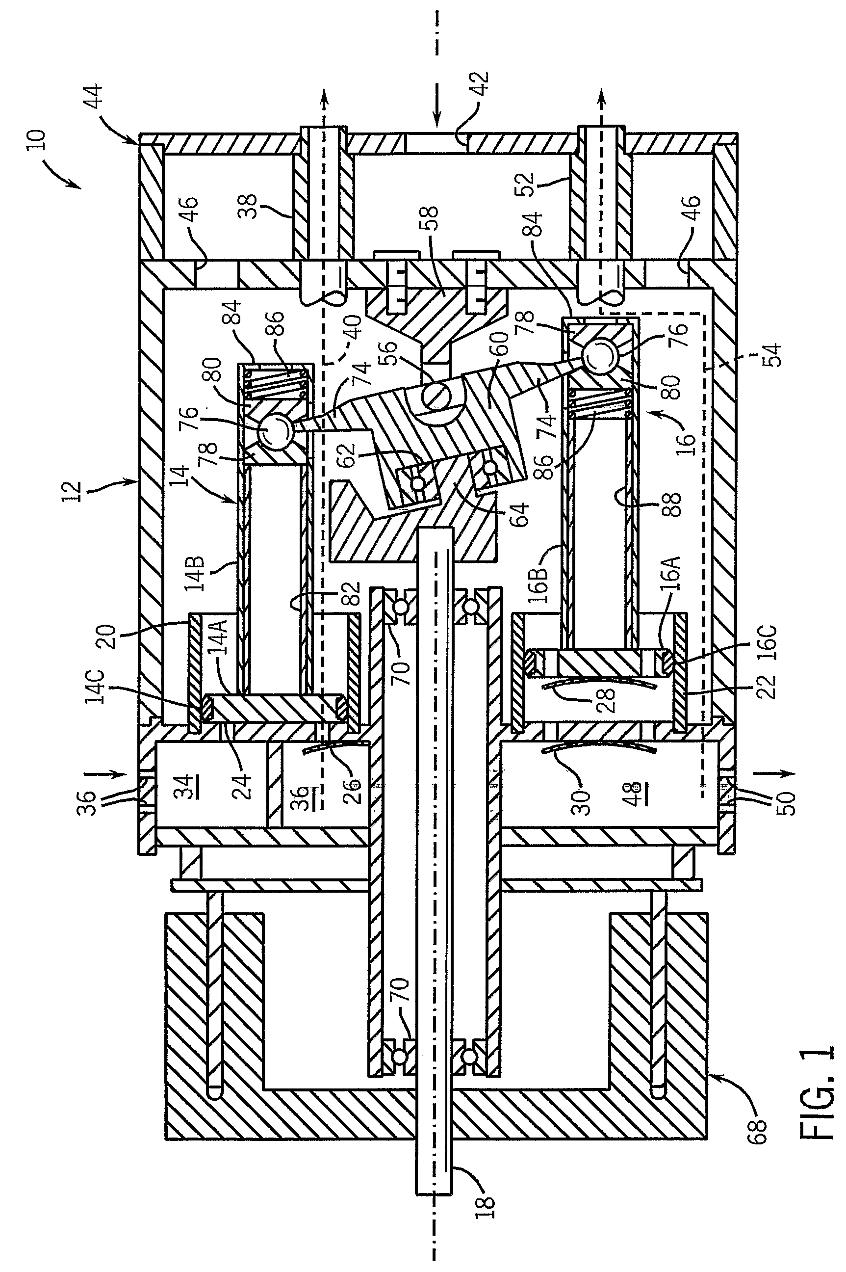
[0011]A pump 10 of the invention has a housing 12 which may be made in any number of pieces, a pair of compression pistons 14 opposite from one another (only one shown, the other one would be 180° apart from the one shown, FIG. 1 being a 90° cross-sectional view), a pair of vacuum pistons 16 (only one shown, the other vacuum piston 16 being opposite from the one shown, 180° spaced therefrom about the axis of drive shaft 18). Each piston 14, 16 has a head 14A or 16A and a rod 14B or 16B, respectively. The heads 14A and 16A reciprocate with a slight wobble motion in respective pump cylinders 20 and 22. Heads 14A and 16A have respective split ring seals 14C, 16C, preferably made of a polytetrafluoroethylene composite material, that establish a sliding seal with the walls of the cylinders 20, 22 and are preferably radiused on their outside surfaces with a radius equal to the cylinder radius to maintain good sealing as the piston wobbles in the cylinder. Intake valve 24 and exhaust valve...


PUM


Abstract

A nutating pump has a cross-type universal joint connecting a nutating member to a pump housing, ball joints connecting the nutating member to piston rods, and the piston rods fixed to piston heads so that the piston heads wobble in pump cylinders.

Description

STATEMENT CONCERNING FEDERALLY SPONSORED RESEARCH OR DEVELOPMENT[0001]Not applicable.FIELD OF THE INVENTION[0002]This invention relates to pumps, and in particular, to nutating pumps.BACKGROUND OF THE INVENTION[0003]Nutating pumps having a nutating member that has a circular rocking or wobble type of motion to reciprocate pistons so as to result in pumping action are known. For example, U.S. Pat. No. 5,007,385 discloses such a mechanism that uses either a spherical bearing or alternatively a cross-type universal joint between the wobble member and the housing. The wobble member is driven eccentrically by a drive shaft and has arms joined by ball joints or other pivot joints to pistons that reciprocate linearly.[0004]These types of mechanisms have typically had many sliding surfaces and, therefore, many bearings, each making the whole construction relatively complex, difficult to assemble, and expensive.SUMMARY OF THE INVENTION[0005]The invention provides a nutating pump in which a c...

Claims


Application Information

Patent Timeline
Patent Type & Authority Patents(United States)
IPC IPC(8): F01B13/04F04B1/12F04B27/10
CPCF04B27/0886F04B27/0895F04B27/1072F04B27/1054Y10T74/18336F01B13/04F04B1/146F04B1/148F04B27/086F04B27/0865F04B27/0869
Inventor LYNN, WILLIAM HARRYFUKSA, RICHARD C.
Owner LYNN WILLIAM HARRY
Learn More