
Method of forming concavities in the surface of a metal component, and related processes and articles

a technology of concavity and metal components, applied in the field of metal components, can solve the problems of increasing the operating temperature of the turbine component, increasing the cooling effectiveness, and causing the failure of the turbine element and destroying the engin

Active Publication Date: 2007-12-04
GE INFRASTRUCTURE TECH INT LLC
View PDF27 Cites 78 Cited by
  • Summary
  • Abstract
  • Description
  • Claims
  • Application Information

AI Technical Summary

Benefits of technology

[0018]One benefit of this invention is it's capability of accurately forming concavities within intricate cooling passages of turbine engine components. Thus, components prepared by the processes described herein represent another embodiment of this invention.

Problems solved by technology

The superalloys usually have an operating temperature limit of about 1000° C.-1150° C. Operation above these temperatures may cause the various turbine elements to fail and damage the engine.
The resulting increase in cooling effectiveness ultimately decreases the operating temperature of the turbine component.
However, in some situations, there are drawbacks associated with this type of feature.
For example, the use of turbulation on some regions of an airfoil surface may undesirably result in a significant pressure loss, due to the effects of friction.
Unfortunately, it can often be extremely difficult to form concavities within some of the interior regions of metal components.
For example, there may be no practical method to form concavities in some regions of the interior flow network of a gas turbine blade.
Moreover, forming a specific pattern of concavities of precise dimensions in those regions has often been impossible.
The concavities are often too small to be cast, e.g., by the investment casting technique used to form the part.
Attempts at casting the concavities may cause other problems as well, like premature die wear.
However, these techniques cannot readily be used to form the features in enclosed, interior regions, because of the lack of easy access.

Method used


Image

  • Method of forming concavities in the surface of a metal component, and related processes and articles
  • Method of forming concavities in the surface of a metal component, and related processes and articles
  • Method of forming concavities in the surface of a metal component, and related processes and articles

Examples


examples

[0075]The following example is provided for illustration, and should not be considered to be any type of limitation on the scope of the present invention.

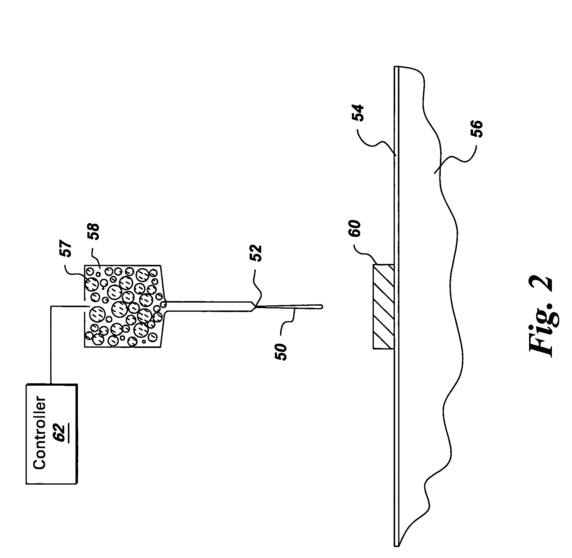
[0076]A Micropen™ device (400 Series), from Ohmcraft, Inc., Honeoye Falls, N.Y.) was used in this example. The pen size was 10 mils (0.25 mm) outer diameter×7 mils (0.18 mm) inner diameter.

[0077]A section of electronic-grade alumina was used as the workpiece / substrate in this example. Its dimensions were about 2 inches×1⅜ inch (5.1 cm×3.5 cm), with a thickness of about 1 mm. The workpiece was positioned on a platform in the device which is movable along X and Y axes via computer-control. The workpiece was held in place by a vacuum.

[0078]The deposition material was alumina / magnesium oxide (10% by weight MgO, based on Al2O3 and MgO combined). It was prepared by dry-mixing powders of the two oxides, and then adding solvent (terpineol), with additional mixing. (The solvent included a small amount of cellulose binder). The amount of sol...


PUM

PropertyMeasurementUnit
operating temperatureaaaaaaaaaa
temperatureaaaaaaaaaa
temperaturesaaaaaaaaaa

Abstract

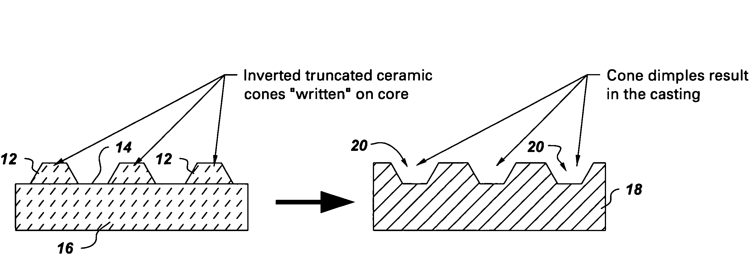
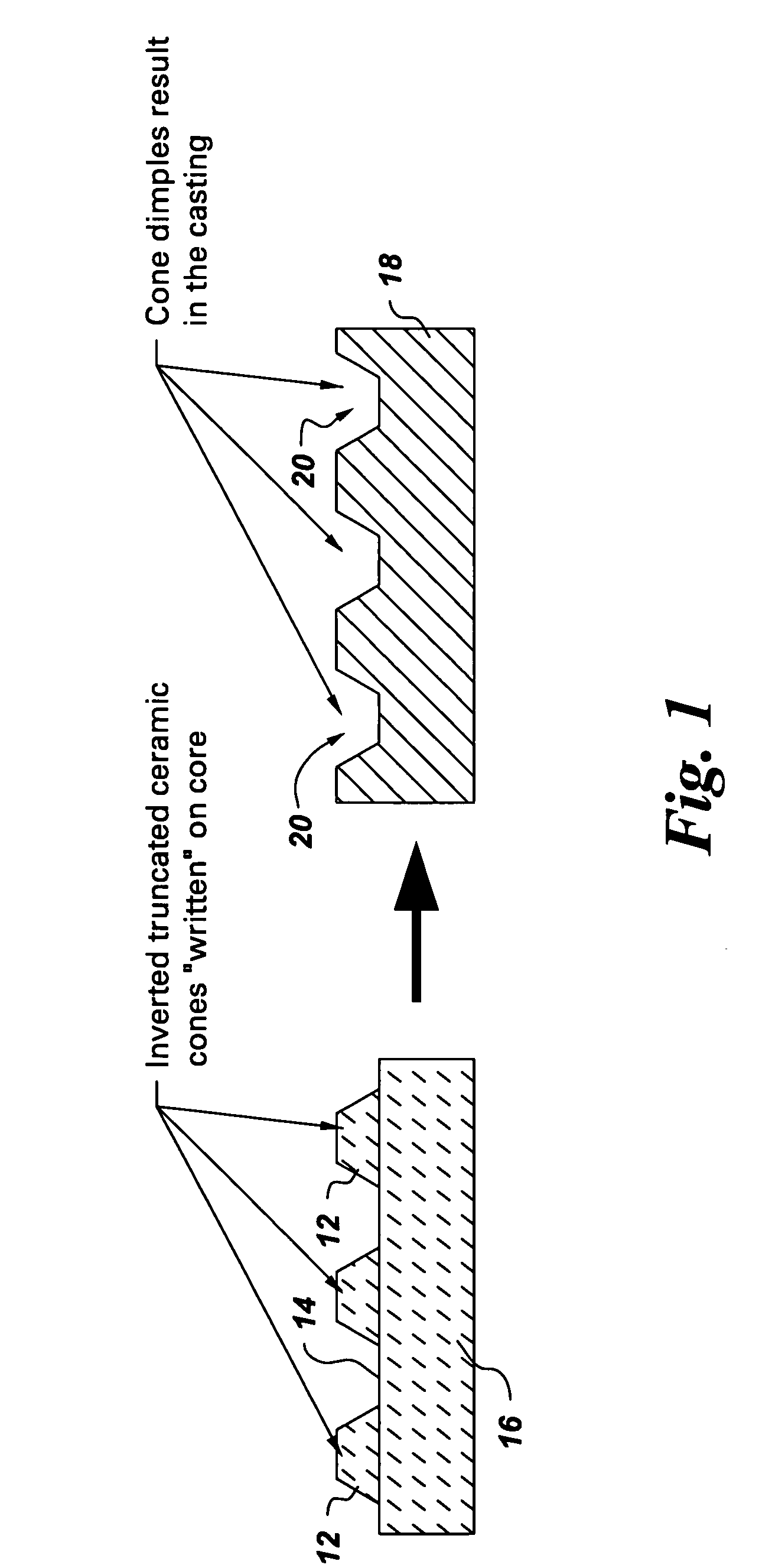
A method of forming at least one concavity of a selected size and shape within a surface of an internal passageway of a metallic component comprises: depositing a ceramic-based material by a direct-write technique onto a ceramic core which is suitable for forming the internal passageway during a casting process to form the metallic component, wherein the ceramic-based material is deposited as a positive feature; heat-treating the deposited ceramic-based material; forming the metallic component by a casting process in which the ceramic core is incorporated into the casting, in a position selected as a desired position for the internal passageway; and then removing the ceramic core from the metal component after the casting process is complete, thereby forming the internal passageway, with the concavity contained within the surface of the passageway, said concavity formed by removal of the positive feature of the ceramic-based material.

Description

TECHNICAL FIELD[0001]This invention generally relates to metal components used in a high-temperature environment. More particularly, the invention is directed to the formation of concavities in hot gas path components for turbine assemblies.BACKGROUND OF THE INVENTION[0002]Various types of metal components are used in high-temperature environments. Turbine engine parts represent examples of these types of components. The parts are usually made by an investment casting process.[0003]Peak temperatures present along the hot gas path of a turbine engine are often maintained as high as possible for operating efficiency. Turbine blades and other elements of the engine are usually made of metal alloys (e.g., superalloys) which can resist the high-temperature environment. The superalloys usually have an operating temperature limit of about 1000° C.-1150° C. Operation above these temperatures may cause the various turbine elements to fail and damage the engine.[0004]The hot gas path componen...

Claims


Application Information

Patent Timeline
Patent Type & Authority Patents(United States)
IPC IPC(8): B22C9/00F01D5/28B22C9/02B22C9/04B22C9/10C04B41/50C04B41/87F02C7/00
CPCB22C9/10C04B41/009C04B41/5031C04B41/87C04B41/4539C04B41/4572C04B41/5029C04B35/04C04B35/10C04B35/14C04B35/18C04B35/565C04B35/48C04B35/584C04B35/481C04B35/505C04B2111/0087F05B2260/222B33Y10/00C23C4/01
Inventor BUNKER, RONALD SCOTTHARDWICKE, CANAN USLULEE, CHING-PANG
Owner GE INFRASTRUCTURE TECH INT LLC
Learn More