In-situ BWR and PWR CRUD flake analysis method and tool

a technology of bwr and pwr, which is applied in the field ofcrud analysis methods and scraping tools, can solve the problems of limiting the effectiveness of removal devices, unintended irradiation of personnel in plant areas, and high radioactivity of crud flake,

a technology of bwr and pwr, which is applied in the field ofcrud analysis methods and scraping tools, can solve the problems of limiting the effectiveness of removal devices, unintended irradiation of personnel in plant areas, and high radioactivity of crud flake,

US7304301B1Inactive Publication Date: 2007-12-04FRAMATOME ANP RICHLAND

Image

  • In-situ BWR and PWR CRUD flake analysis method and tool
  • In-situ BWR and PWR CRUD flake analysis method and tool
  • In-situ BWR and PWR CRUD flake analysis method and tool

Examples


Embodiment Construction

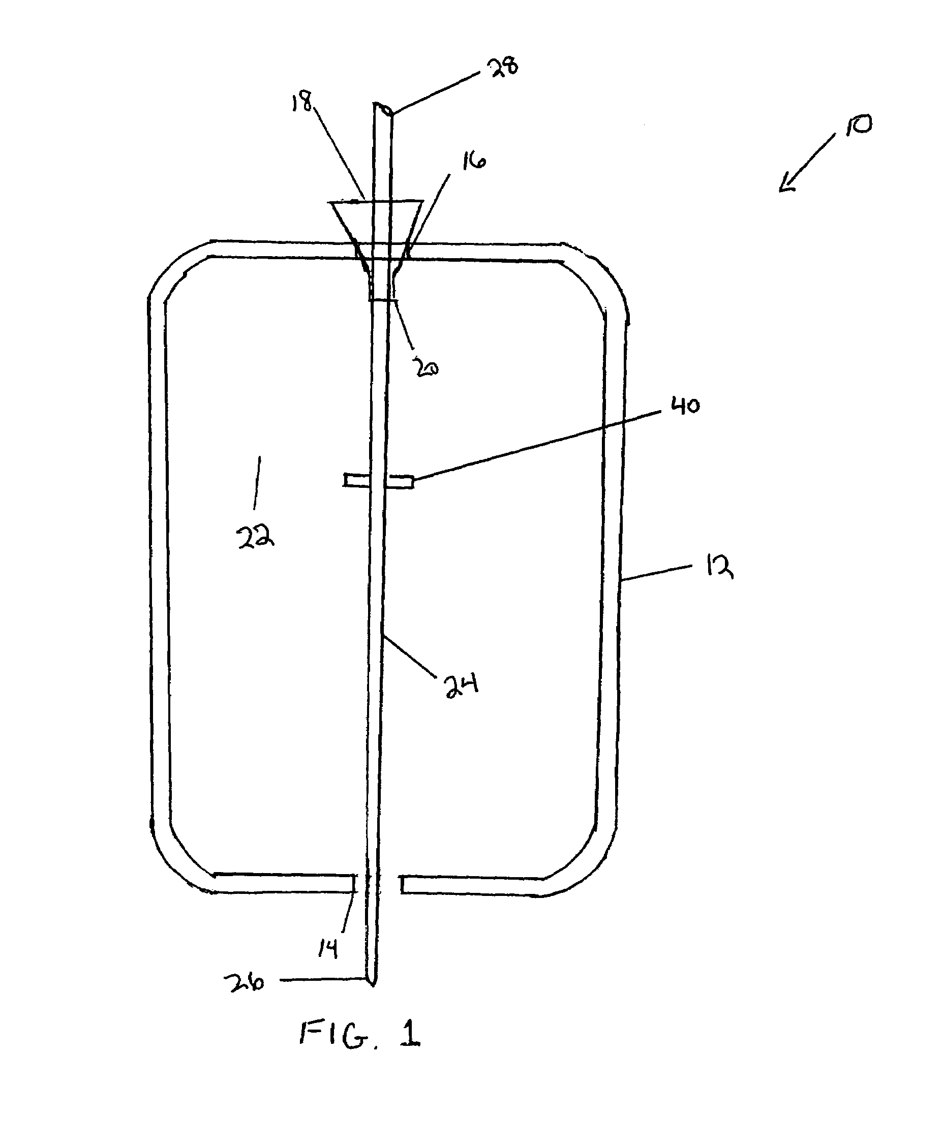
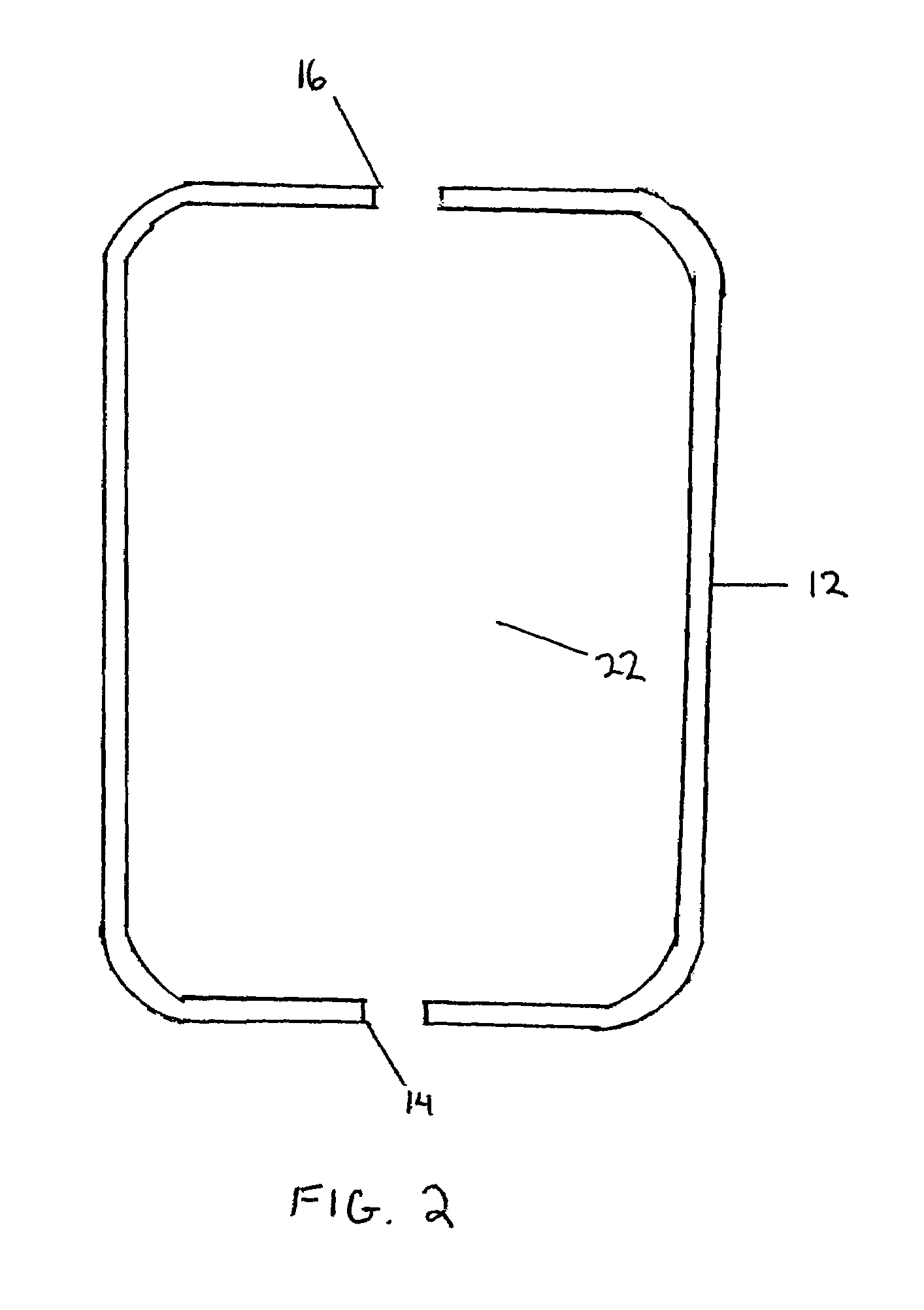
[0033]Referring to FIG. 1, a CRUD removal device 10 is illustrated. The CRUD removal device 10 allows CRUD to be removed from an exterior of a nuclear fuel rod 24 in a safe and controlled environment. The CRUD removal device 10 allows the CRUD to be removed in a nuclear fuel pool of a nuclear facility, for example, such that loose or firmly attached CRUD may be dislodged. The CRUD removal device 10 further allows the CRUD to be dislodged without removing warped zircalloy material from the stabilized zircalloy substrate. The device 10 may be made of materials, such as stainless steel, to hinder potential corrosion. A blade 40 is placed in the CRUD removal device 10 such that the fuel rod 24 runs over the blade 40 to facilitate removal of the CRUD layer. Although shown as a single blade 40, multiple blades may be used. A housing 12 defines an interior volume 22 which allows the fuel rod 24 to be partially contained within the housing 12. The fuel rod 24 penetrates the housing 12 throu...


PUM

PropertyMeasurementUnit
sensitivityaaaaaaaaaa
diameteraaaaaaaaaa
diameteraaaaaaaaaa

Abstract

The invention provides a method and tool to perform an analysis of CRUD on a nuclear fuel rod. The method recites providing a nuclear fuel rod with a layer of CRUD on an exterior of the fuel rod, scraping the CRUD from the fuel rod with a CRUD scraping tool and collecting CRUD flakes from the CRUD scraping tool. The method also provides for sorting the CRUD flakes into particle fractions, and analyzing the CRUD with a scanning electron microscope, wherein the scraping tool has a blade with a rigidity that is matched to an anticipated CRUD deposit shear strength.

Description

CROSS-REFERENCE TO RELATED APPLICATION[0001]This application is a divisional of U.S. application Ser. No. 10 / 830,913, filed Apr. 23, 2004 now U.S. Pat. No. 7,132,651, herein incorporated by reference.FIELD OF THE INVENTION[0002]The current invention relates to a CRUD analysis method and tool. More specifically, the current invention provides a CRUD analysis methodology and a scraping tool for nuclear fuel rods to determine physical properties of CRUD deposited on an exterior of a nuclear fuel rod.BACKGROUND INFORMATION[0003]Nuclear reactors, such as pressurized water reactors and boiling water reactors, generate nuclear power through the use of nuclear fuel assemblies housed in a reactor core. The fuel assemblies are comprised of elongated hollow metallic tubular fuel rods that contain pellets of enriched uranium dioxide material. The hollow metallic fuel tubular rods, commonly known in the nuclear industry as cladding, prevent the escape of materials, such as uranium dioxide and fi...

Claims


Application Information

Patent Timeline
04 Dec 2007
Publication
US7304301B1
IPC
G01N1/28; G01N23/225
CPC
G01N1/04; G01N23/225; G21C17/06; G01N2001/2873; G21Y2004/501; G21Y2002/303; G21Y2002/304; G21Y2002/501
Inventors
POP, MIHAI G. M.; LOCKAMON, BRIAN G.