
Magnetic carrier and two component developer

a technology of two components and carriers, applied in the field of magnetic carriers and two component developers, can solve the problems of deterioration of developers, easy occurrence, image density variation, etc., and achieve the effect of excellent reproducibility and high quality

Active Publication Date: 2011-04-19
CANON KK
View PDF12 Cites 56 Cited by
  • Summary
  • Abstract
  • Description
  • Claims
  • Application Information

AI Technical Summary

Benefits of technology

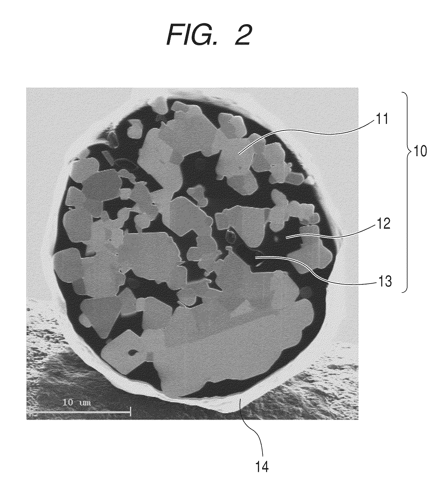
The present invention provides a magnetic carrier and a two component developer that are free from problems such as density variation, fogging, and carrier adhesion. The magnetic carrier has magnetic carrier particles with specific properties, and the two component developer contains the magnetic carrier and toner. Using this new magnetic carrier and developer, a high quality image can be formed stably with excellent dot reproducibility even during long-term use.

Problems solved by technology

However, such a carrier has a high density and further a large saturated magnetization, and thus a magnetic brush becomes so stiff that deterioration of a developer, such as carrier spent and deterioration of an external additive for toner, can take place easily.
However, the thus ground down carriers increase in the developer during long-term use thereby decreasing the fluidity of the developer and this, in turn, causes image density variation (a decrease in image uniformity) and fogging in some cases.
However, the laminated structure is so dense that filling the void part present near to the center of a core material with a resin is prone to be insufficient.
As a result, there has been a case that part of the magnetic carrier was destroyed during long-term durability use, leading to carrier adhesion.
Furthermore, the carrier is excessively charged due to the presence of voids, and thus the need still exists to obtain a high quality image stably.

Method used


Image

  • Magnetic carrier and two component developer
  • Magnetic carrier and two component developer
  • Magnetic carrier and two component developer

Examples


production example 2

of the Porous Magnetic Core

[0206]In the production example 1 of the porous magnetic core, the following conditions were changed. Namely, in Step 3, the degree of crushing particles in the crusher was changed from about 0.3 mm to about 0.5 mm, the balls in the wet-type ball mill were changed from stainless steel with a 10 mm diameter (φ) to zirconia with a 10 mm diameter (φ), and the crushing time was changed from one hour to two hours. The crushing time in the wet-type bead mill was changed from one hour to two hours. In Step 5, the calcination temperature was changed from 1,100° C. to 1,050° C. and the time for raising the temperature from a room temperature to the calcination temperature was changed from 3 hours to 2 hours. The other conditions were made as same as those in the production example 1 of the porous magnetic core to obtain the porous magnetic core 2. The obtained physical properties are shown in Table 1.

production example 3

of the Porous Magnetic Core

[0207]In the production example 1 of the porous magnetic core, the following conditions were changed. Namely, in Step 3, the degree of crushing particles in the crusher was changed from about 0.3 mm to about 0.5 mm, the balls in the wet-type ball mill were changed from stainless steel with a 10 mm diameter (φ) to zirconia with a 10 mm diameter (φ), and the crushing time was changed from one hour to two hours. The crushing time in the wet-type bead mill was changed from one hour to three hours. In Step 4, 2.0 parts by mass of sodium carbonate was added as a pore controlling agent along with 2.0 parts by mass of polyvinyl alcohol as a binder to the ferrite slurry. In Step 5, the calcination temperature was changed from 1,100° C. to 1,050° C. The other conditions were made as same as those in the production example 1 of the porous magnetic core to obtain the porous magnetic core 3. The obtained physical properties are shown in Table 1.

production example 4

of the Porous Magnetic Core

[0208]In the production example 1 of the porous magnetic core, the following conditions were changed. Namely, in Step 3, the degree of crushing particles in the crusher was changed from about 0.3 mm to about 0.5 mm, the balls in the wet-type ball mill were changed from stainless steel with a 10 mm diameter (φ) to zirconia with a 10 mm diameter (φ), and the crushing time was changed from one hour to three hours. The beads in the wet-type bead mill were changed from zirconia with a 1.0 mm diameter (φ) to alumina with a 1.0 mm diameter (φ) and the crushing time was changed from one hour to two hours. In Step 4, 0.5 parts by mass of sodium carbonate was added as a pore controlling agent along with 2.0 parts by mass of polyvinyl alcohol as a binder to the ferrite slurry. In Step 5, the calcination temperature was changed from 1,100° C. to 1,050° C. and the calcination time was changed from 4 hours to 2 hours. The other conditions were made as same as those in t...


PUM


Abstract

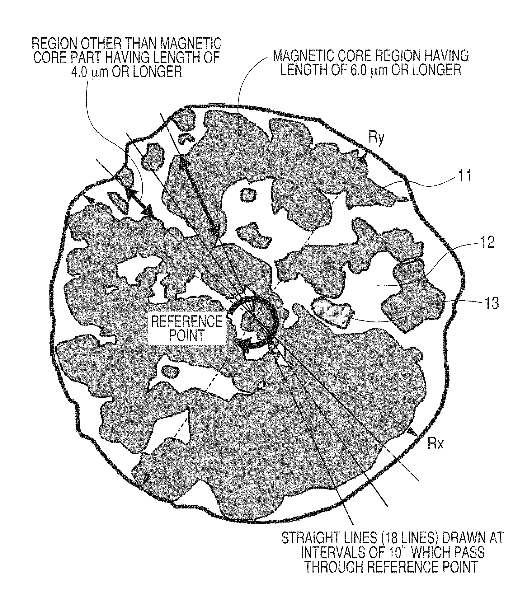
Provided is a magnetic carrier giving a high quality image free of density variation without the occurrence of fogging or carrier adhesion and having excellent dot reproducibility even during long-term use. The magnetic carrier has magnetic carrier particles produced by filling pores of porous magnetic core particles with a resin. The magnetic carrier contains 80% by number or more of the magnetic carrier particles satisfying the specific conditions (a) and (b) when 18 straight lines passing through a reference point of a cross section of the magnetic carrier particle are drawn at intervals of 10° in a reflected electron image of the cross section of the magnetic carrier particle photographed by a scanning electron microscope.

Description

[0001]This application is a continuation of International Application No. PCT / JP2009 / 064092, filed on Aug. 4, 2009, which claims the benefit of Japanese Patent Application No. 2008-200644 filed on Aug. 4, 2008.BACKGROUND OF THE INVENTION[0002]1. Field of the Invention[0003]The present invention relates to a magnetic carrier and a two component developer used for an electrophotographic method, an electrostatic recording method, and an electrostatic printing method.[0004]2. Description of the Related Art[0005]For example, a ferrite carrier containing a heavy metal has conventionally been used as a carrier. However, such a carrier has a high density and further a large saturated magnetization, and thus a magnetic brush becomes so stiff that deterioration of a developer, such as carrier spent and deterioration of an external additive for toner, can take place easily.[0006]Accordingly, in order to lower specific gravity, a carrier having a surface having very small asperities and an inne...

Claims


Application Information

Patent Timeline
Patent Type & Authority Patents(United States)
IPC IPC(8): G03G9/00
CPCG03G9/0819G03G9/0821G03G9/107G03G9/1136G03G9/113G03G9/1132G03G9/1075G03G9/1085G03G9/08G03G9/1131
Inventor KOMATSU, NOZOMUISHIGAMI, KOHFUJIKAWA, HIROYUKINAKAMURA, KUNIHIKOINOUE, CHIKABABA, YOSHINOBUITAKURA, TAKAYUKIENDO, TOMOKO
Owner CANON KK
Learn More