
Balanced amplifier

a balanced power amplifier and amplifier technology, applied in push-pull amplifiers, negative-feedback circuit arrangements, phase-splitters, etc., can solve the problems of little development of vacuum tube balanced power amplifiers, amplifier instability, and different sound quality of semiconductor audio amplifiers

Inactive Publication Date: 2007-12-04
LAM CHI MING JOHN
View PDF11 Cites 10 Cited by
  • Summary
  • Abstract
  • Description
  • Claims
  • Application Information

AI Technical Summary

Benefits of technology

[0008]It is thus an object of the present invention to provide a balanced amplifier in which the aforesaid shortcomings are mitigated or at least to provide a useful alternative. In particular, the present invention provides a new balanced amplifier topology that can be employed in vacuum tube power amplifier applications for improving performance.

Problems solved by technology

However, the sound quality of semiconductor audio amplifiers is different from vacuum tube audio amplifier, and many audio consumers prefer the sound of amplifiers using vacuum tubes to those using semiconductors.
However, there has been very little development on vacuum tube balanced power amplifiers.
However, it is well known that if too much feedback is applied, it will render instability to the amplifier.
Although these are all desirable features, as stated above, applying too much feedback will create instability to the amplifier, whereas applying too little feedback will not obtain the desired results.
A designer thus always has difficulty in optimizing the overall power performance by using a single pair of feedback loops.

Method used


Image

  • Balanced amplifier
  • Balanced amplifier
  • Balanced amplifier

Examples


Embodiment Construction

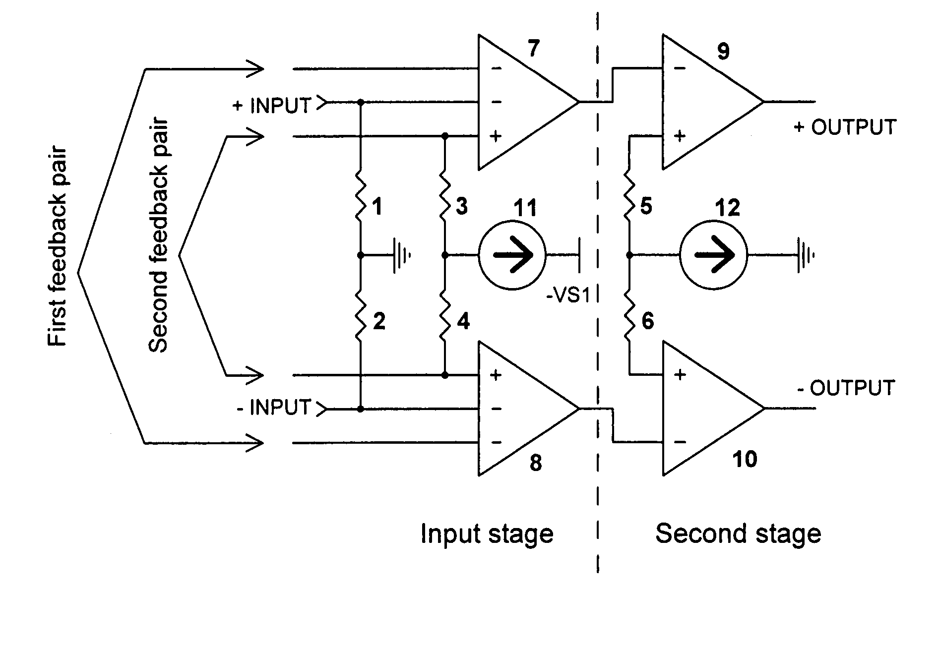
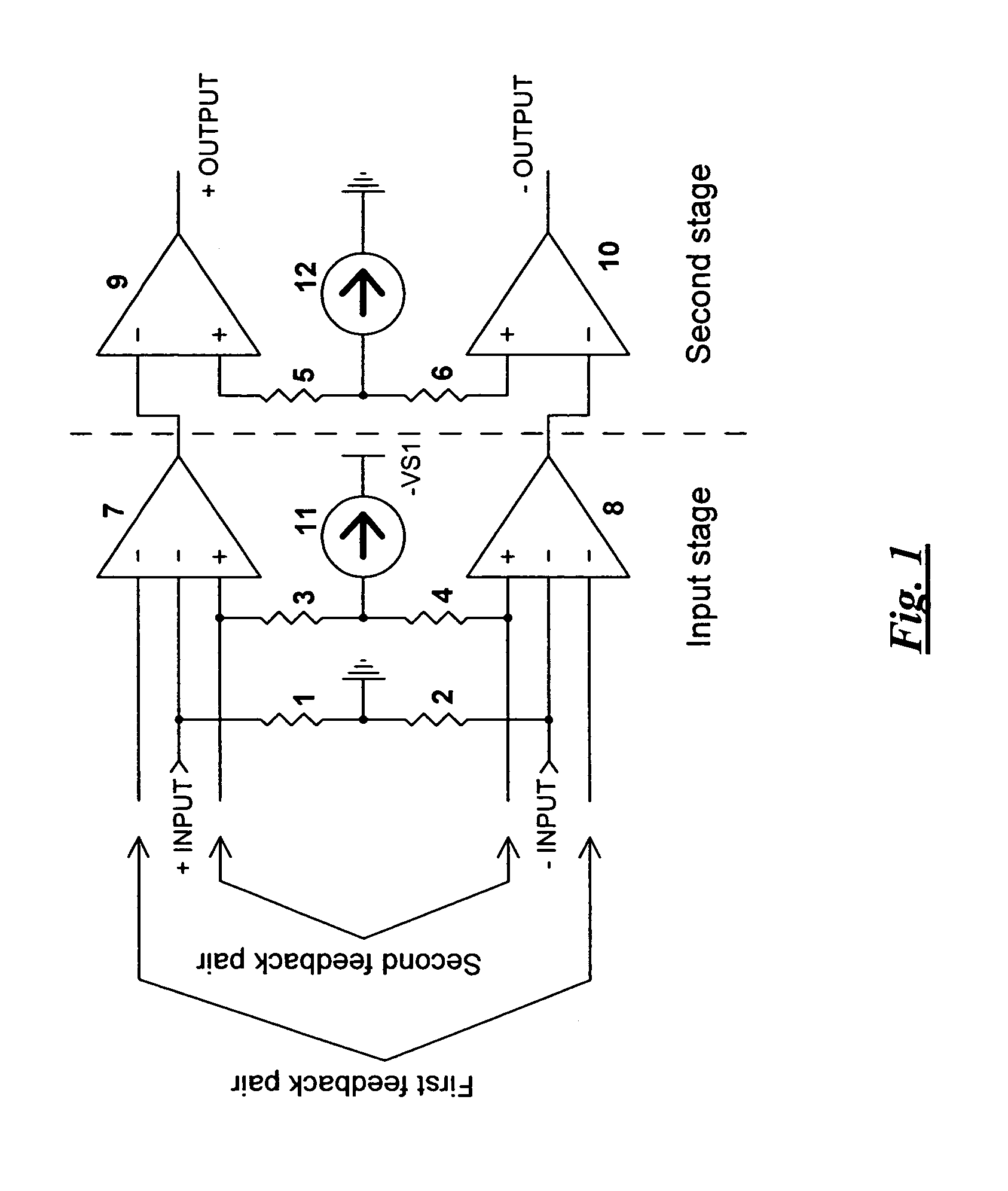
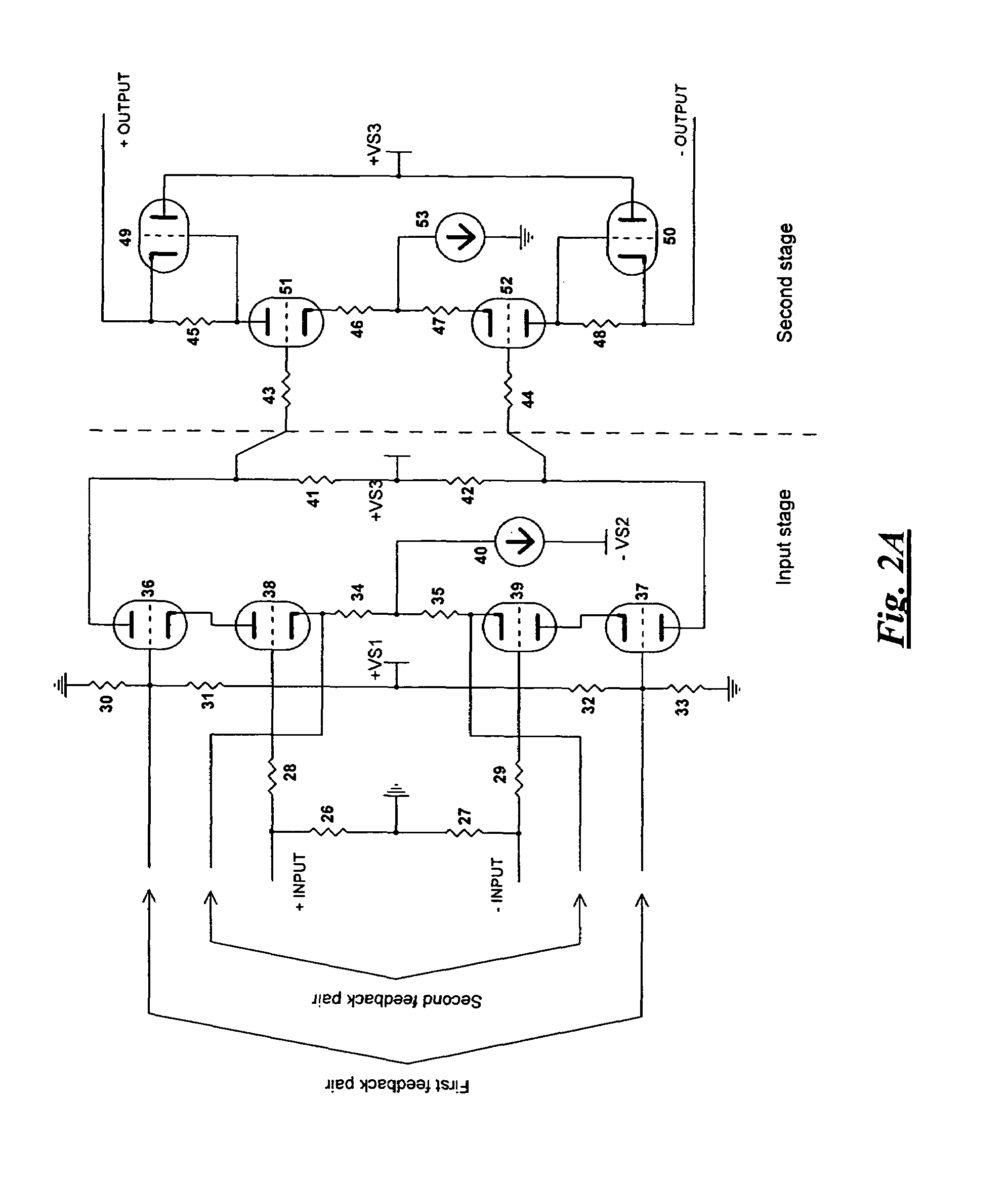
[0024]A functional block diagram of a vacuum tube balanced amplifier according to a first embodiment of the present invention is shown in FIG. 1, and a detailed circuitry thereof shown in FIG. 2A.

[0025]As shown in FIG. 1, the first stage, which is a special type of differential amplifier, contains amplifying devices 7 and 8, resistors 1, 2, 3 and 4 and a current source 11. The first stage accepts balanced input signals (+INPUT &−INPUT) and provides two feedback pairs for signals on the following stage(s) to feedback portion of the output signals to this first stage.

[0026]The second stage, which is another type of special differential amplifier, contains amplifying devices 9 and 10, resistors 5 and 6, and a current source 12. The second stage amplifies the balanced signals from the first stage and maintains the balanced signals for the following amplifying stage or stages, if any.

[0027]More details are shown in FIG. 2A. The balanced amplifier includes four pairs of dual vacuum tubes,...


PUM


Abstract

A balanced amplifier is disclosed as comprising an input stage connected with a second stage, in which the input stage outputs signals to the second stage, and the first stage includes a first differential amplifier for receiving balanced input signals and is provided with two pairs of feedback loops, at least one of the pair of feedback loops for feedbacking part of signals outputted by the second stage to the first differential amplifier, and the second stage includes a second differential amplifier for amplifying signals received from the first stage and for maintaining the balanced signals.

Description

CROSS-REFERENCE TO RELATED APPLICATION[0001]This application claims the benefit of the filing date of United Kingdom Patent Application No. 0600146.5 filed 5 Jan. 2006, the disclosure of which is hereby incorporated by reference.BACKGROUND OF THE INVENTION[0002]Semiconductor-based audio power amplifiers have been dominating the audio market since late 1960's. Advantages of employing semiconductor devices in audio signal amplification include compact size, cost effective power handling and high output power. However, the sound quality of semiconductor audio amplifiers is different from vacuum tube audio amplifier, and many audio consumers prefer the sound of amplifiers using vacuum tubes to those using semiconductors. In the high-end audio market, vacuum tube audio systems have gained a very favourable market share since its return in the late 1980's.[0003]In the high-end audio applications, balanced topologies are often used in semiconductor amplifiers, both power and low-level (i.e...

Claims


Application Information

Patent Timeline
IPC IPC(8): H03F3/45
CPCH03F3/45H03F3/22H03F1/36H03F3/28
Inventor LAM, CHI MING JOHN
Owner LAM CHI MING JOHN
Learn More