Peak suppression of multi-carrier signal with different modulation

a multi-carrier signal and modulation technology, applied in the field of peak suppression, phase and amplitude equalizer circuits, can solve the problems of high power consumption, cost and size of the system, increase the power consumption of the system, and increase so as to reduce the peak to average ratio, the effect of boosting the power handling of the amplifier and acting more linearly

Active Publication Date: 2007-12-04
ALTERA CORP
View PDF9 Cites 6 Cited by
  • Summary
  • Abstract
  • Description
  • Claims
  • Application Information

AI Technical Summary

Benefits of technology

[0002]According to the invention, a peak suppression, phase and amplitude equalizer circuit, used for multi-carrier signals, where individual carriers use different modulation and bandwidth, uses a plurality of simple and accurate circuits in conjunction with intelligent signal processing to reduce the peak to average ratio without disturbing the properties of the multi-carrier signal. By intelligent, it is meant that the peak suppression, phase and amplitude equalizer module has features of adaptability to the input samples, such as ability to consider the changes due to samples amplitude and phase. The peak suppression, phase and amplitude equalizer module uses the amplifier input which could be a baseband, an IF or RF signal as its input and condition the input before applying to the multi-carrier amplifier. The conditioning or peak suppression, phase and amplitude equalizer helps to boost the power handling of the amplifier or acts more linearly. The conditioning is based on a hybrid technique that utilizes both amplitude clipping and phase rotation using pre-defined parameters stored in a lookup table for peak-to-average reduction. The input to the peak suppression, phase and amplitude equalizer should be within a limit that can be handled by the peak suppression, phase and amplitude equalizer module.

Problems solved by technology

This component has a major contribution in cost, power consumption, and size of the system.
The higher the linearity, the higher the power consumption, cost and size.

Method used


Image

  • Peak suppression of multi-carrier signal with different modulation
  • Peak suppression of multi-carrier signal with different modulation
  • Peak suppression of multi-carrier signal with different modulation

Examples


Embodiment Construction

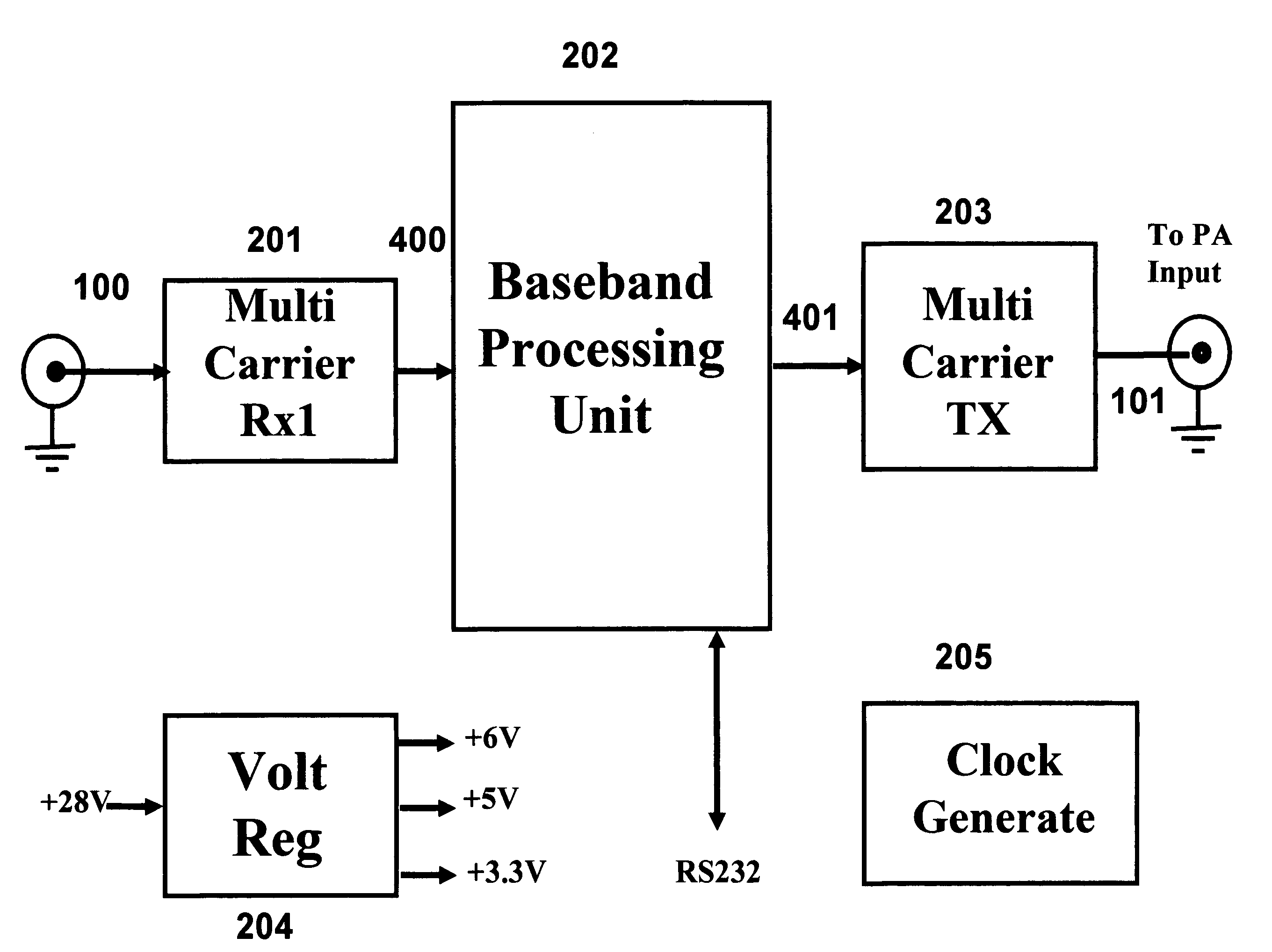
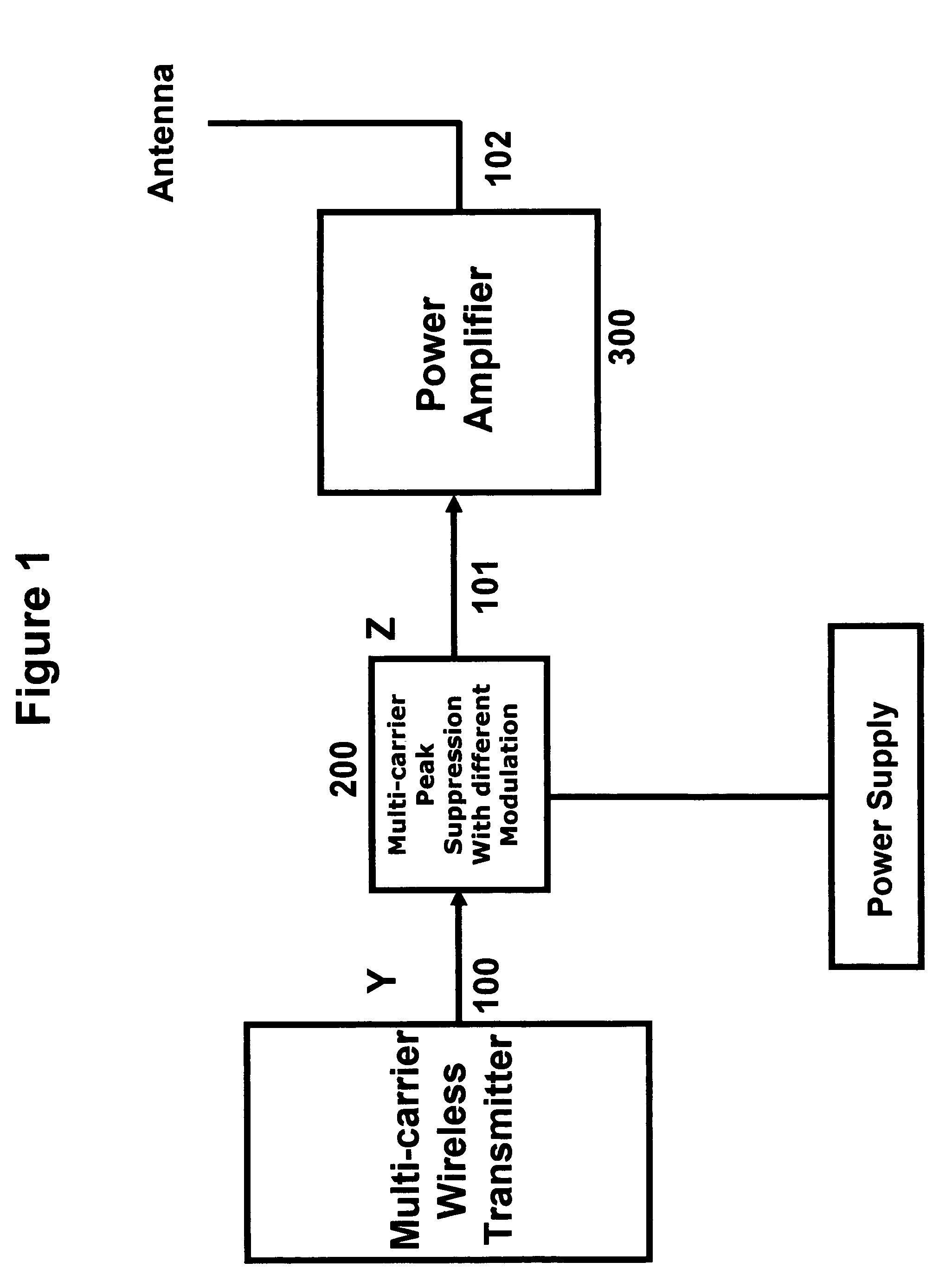
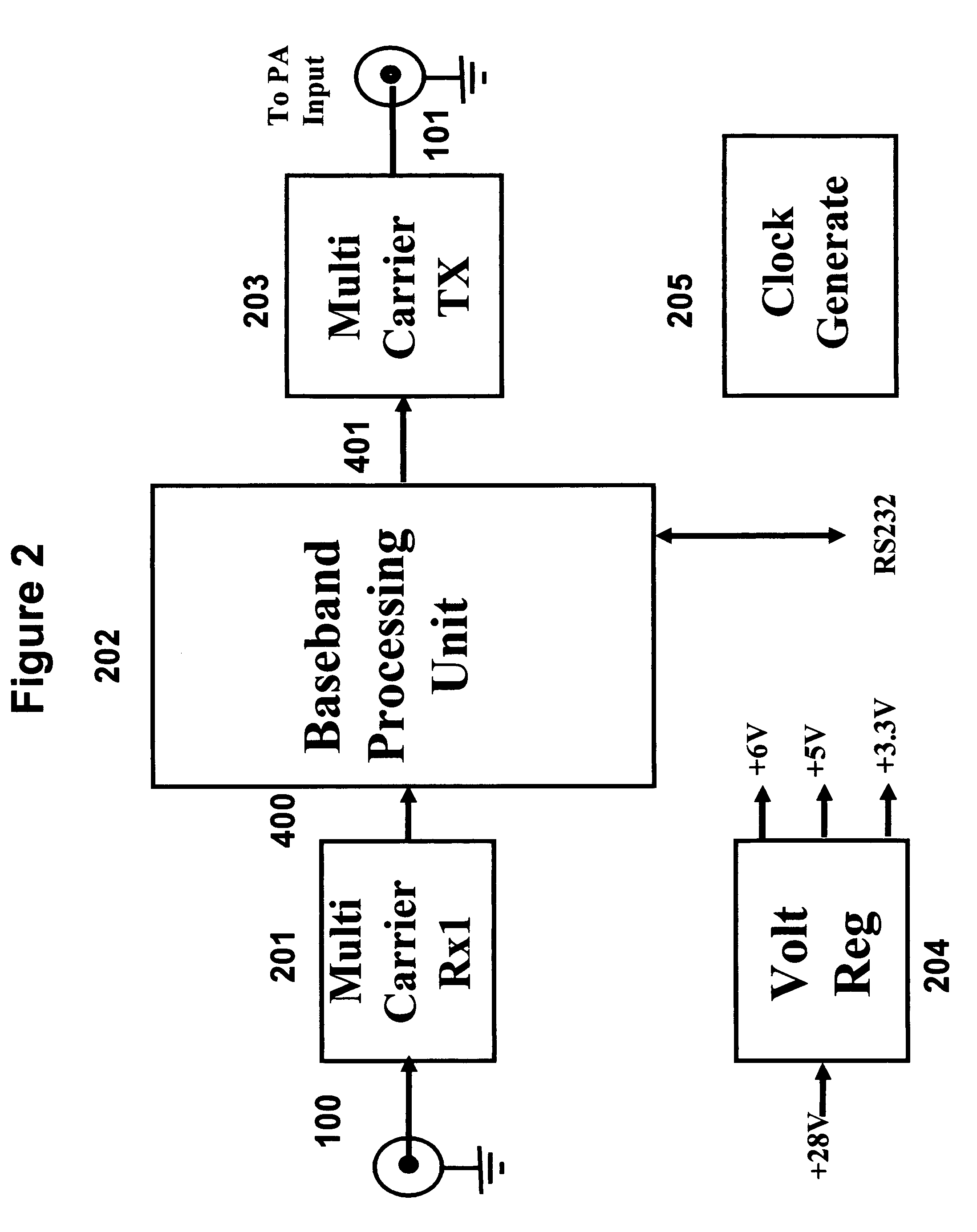
[0010]In a first preferred embodiment the peak suppression, phase and amplitude equalizer circuit monitors the signal strength of the multi-carrier input signal channels using the input receiver and finds the frequency and channel number of the input signals. In a second preferred embodiment of the invention, the peak suppression, phase and amplitude equalizer circuit uses sub-harmonic sampling to convert multi-carrier RF or IF signals to digital baseband signal. In a third preferred embodiment the input signal is conditioned or peak suppressed using the amplitude clipping, phase rotation, and amplitude and phase equalization. The peak-to-average reduction using phase rotation is based on data stored in a lookup table and an algorithm to define the final phase rotation for individual carriers. The peak-to-average reduced signal is then transmitted to the amplifier. In a fourth embodiment the input signal is used to create the lookup table. In a fifth embodiment the digital baseband ...


PUM


Abstract

A technique for peak suppression, phase and amplitude equalizer of multi-carrier signals with different modulation is described. The input to the multi-carrier power amplifier is modified by a peak suppression, phase and amplitude equalizer circuit prior to being applied to the amplifier. The peak suppression is applied to a multi-carrier signal with different modulations and bandwidth. After peak suppression each individual carrier is phase and amplitude equalized to maintain the properties of the multi-carrier signal. The phase equalizer maintain the timing property of the carriers and the amplitude equalizer maintain the modulation accuracy of the individual carriers. The input to the peak-to-average reduction circuit could be a baseband, an intermediate frequency (IF) or radio frequency (RF) signal. The peak-to-average reduction is performed in digital domain.

Description

BACK GROUND OF INVENTION[0001]The present invention relates to a peak suppression, phase and amplitude equalizer circuit to boost the out put power of a multi-carrier wireless RF power amplifier. The peak suppression, phase and amplitude equalizer circuit input could be baseband, intermediate frequency (IF), or RF signal, and its output is the peak-to-average reduced RF signal as a new input to the amplifier. In any wireless communication system one of the critical components is the power amplifier. This component has a major contribution in cost, power consumption, and size of the system. The main reason is the requirement of wireless radio communication system for linear power amplifiers. The higher the linearity, the higher the power consumption, cost and size. In order to minimize the cost, size and power consumption there is a need for techniques that overcome this problem. This invention conquers these challenges by using a simple and accurate peak suppression, phase and ampli...

Claims


Application Information

Patent Timeline
Patent Type & Authority Patents(United States)
IPC IPC(8): H04K1/10H01Q11/12H03F1/26H03F1/36H03G3/20H04B1/04H04B1/38H04K1/02H04L27/26
CPCH04L27/2614
Inventor ANVARI, KIOMARS
Owner ALTERA CORP
Why Eureka
Try Eureka