Thermal drill cuttings treatment with weir system

a weir system and drilling cutting technology, applied in the direction of centrifuges, borehole/well accessories, separation processes, etc., can solve the problems of increasing wear on mud pumps and other mechanical equipment used for drilling, increasing the difficulty of cuttings on-site at an offshore rig, and increasing the cost of operation, so as to reduce the size of condensing and particulate collection equipment and high hydrocarbon contamination

Inactive Publication Date: 2007-12-11
VARCO I P INC
View PDF75 Cites 57 Cited by
  • Summary
  • Abstract
  • Description
  • Claims
  • Application Information

AI Technical Summary

Benefits of technology

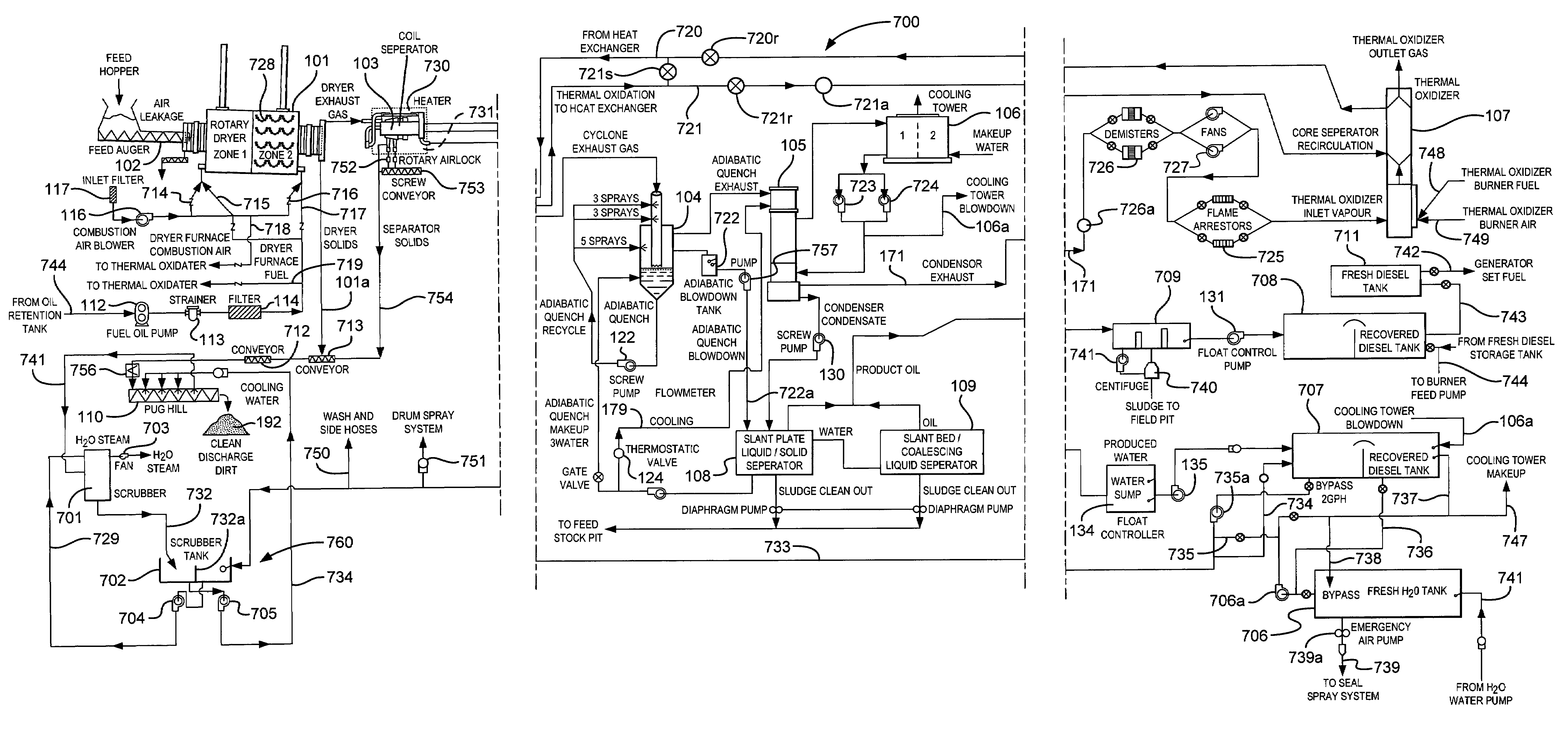
[0012]The condenser subsystem processes the exhaust gas stream produced by heating and volatilizing of the material in the heater dryer and by separation by the dual component separator. The dual component separator removes fines such as dust and other fine particulates from a stream flowing from the thermal treatment system to the oil / water separator to prevent such particulates from remaining in an oil stream produced by the oil / water separator and / or from an exhaust stream, producing a clean discharge. A suitable typical blower or air mover may be used to pull the stream from the heater dryer to the dual component separator, and / or to the other component(s) and separator(s). Recovered water may, according to the present invention, be used, e.g., for re-hydration of cuttings or added to the drilling fluid. Recovered oil may be used to fire burners, or as a mud additive. Recovered diesel may be used to fire the heater dryer. Any oil separator may have an exhaust that is fed to a burner and / or to an exhaust stack.
[0016]Either indirect or direct fired dryers may be used. The use of indirect dryers (vs. direct convection type dryers) allow for higher hydrocarbon contamination in the material to be treated. Some convection dryers have operational limits between 3% and 5% hydrocarbon contamination in the material to be treated. Also, some indirect dryers do not combine the dryer burner by-product of combustion gas with steam and sweep gas, reducing the size of the condensing and particulate collection equipment.
[0018]In one aspect, a soil recycling facility has on-site laboratory equipment to validate that the soils are properly remediated along with proper storage arrangements for the materials awaiting processing. A remediation plant according to the present invention may include: material holding hoppers, material handling conveyors and equipment, rotary dryer(s), soil conditioner(s) (adding water), heat exchanger(s), oil / water treatment(s), particulate separation and collection, and controls. Advantages of such systems include: remediation and recycling of the soil; removal and recycling of hydrocarbons; high levels of hydrocarbon removal and state-of-the-art pollution control; reliable and cost effective option to landfill disposal; reuse of the remediated soil, water, and hydrocarbons in a variety of ways; certification of remediation of hydrocarbon contaminated soils; ability to process a wide variety of types of cuttings, soils and hydrocarbons; maintenance of the ambient air quality standards.
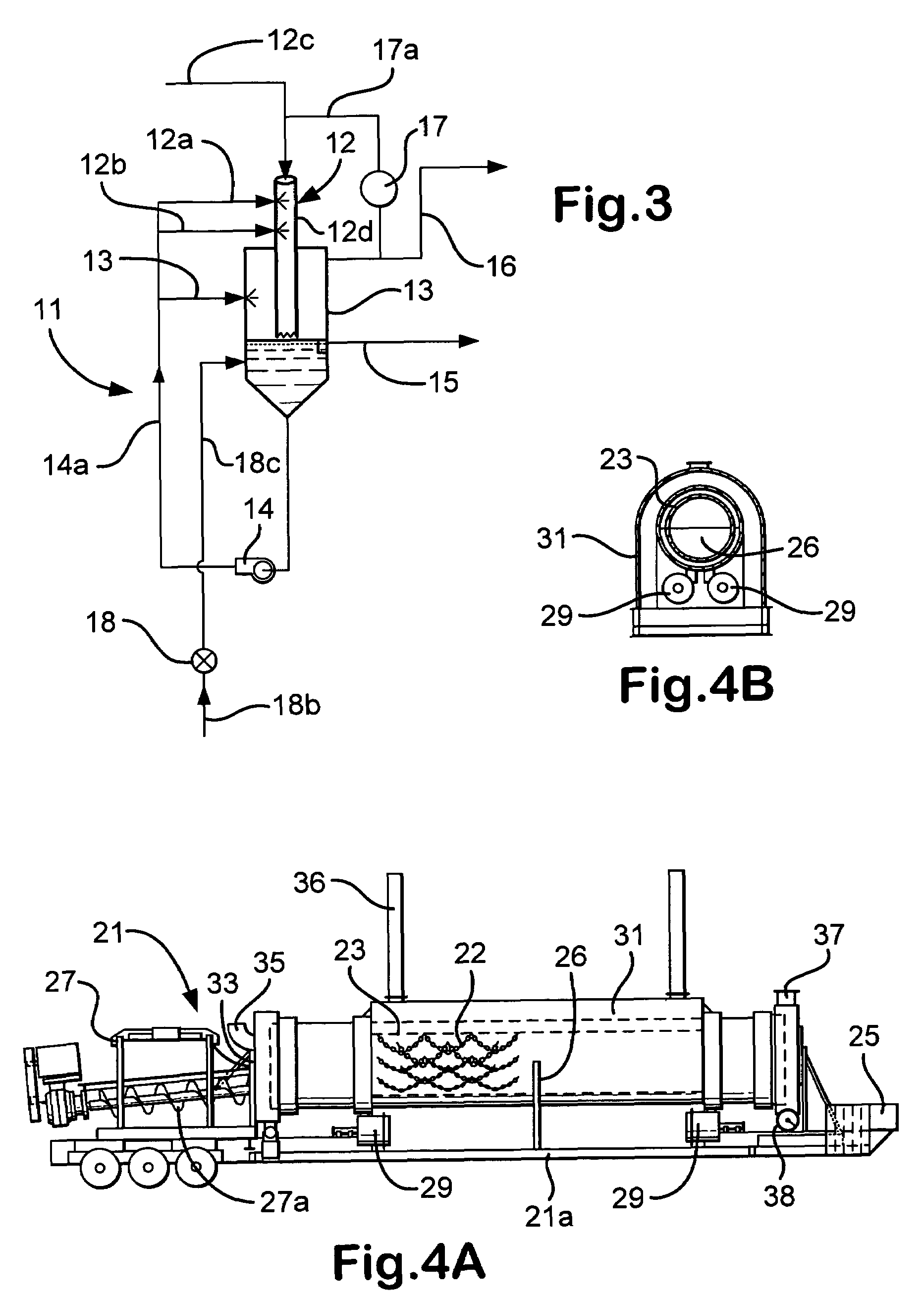
[0022]In one particular embodiment, a rotary dryer according to the present invention has an outer shell or case which internally is divided by a wall into two interior chambers. Temperature in each chamber can be controlled providing dual evaporating temperatures. This permits control over the vaporization process and more even heating of the drum and inhibits or prevents overheating of the hot end of the drum while attempting to get the cold end hot. Burners and / or fireboxes may be provided like any of those disclosed in the prior art or, according to the present invention, one or more burners are provided, either in separate fireboxes (as require by U.S. Pat. No. 5,927,970—which separate fireboxes are not the legal equivalent of burners mounted within the dryer shell or case, burners not in separate fireboxes; said patent incorporated fully herein for all purposes) or within the shell of the dryer; at one or at both ends of the shell or case. This can reduce or eliminate hot spots and flame impingement on the drum.

Problems solved by technology

If drilled solids are not removed from the mud used during the drilling operation, recirculation of the drilled solids can create weight, viscosity, and gel problems in the mud, as well as increasing wear on mud pumps and other mechanical equipment used for drilling.
Remediation of cuttings on-site at an offshore rig is a difficult and expensive operation.
Often in direct processes, volatile contaminants are destroyed by direct flame contact and a portion of them may be thermally destroyed in a downstream oxidizer.

Method used


Image

  • Thermal drill cuttings treatment with weir system
  • Thermal drill cuttings treatment with weir system
  • Thermal drill cuttings treatment with weir system

Examples


Embodiment Construction

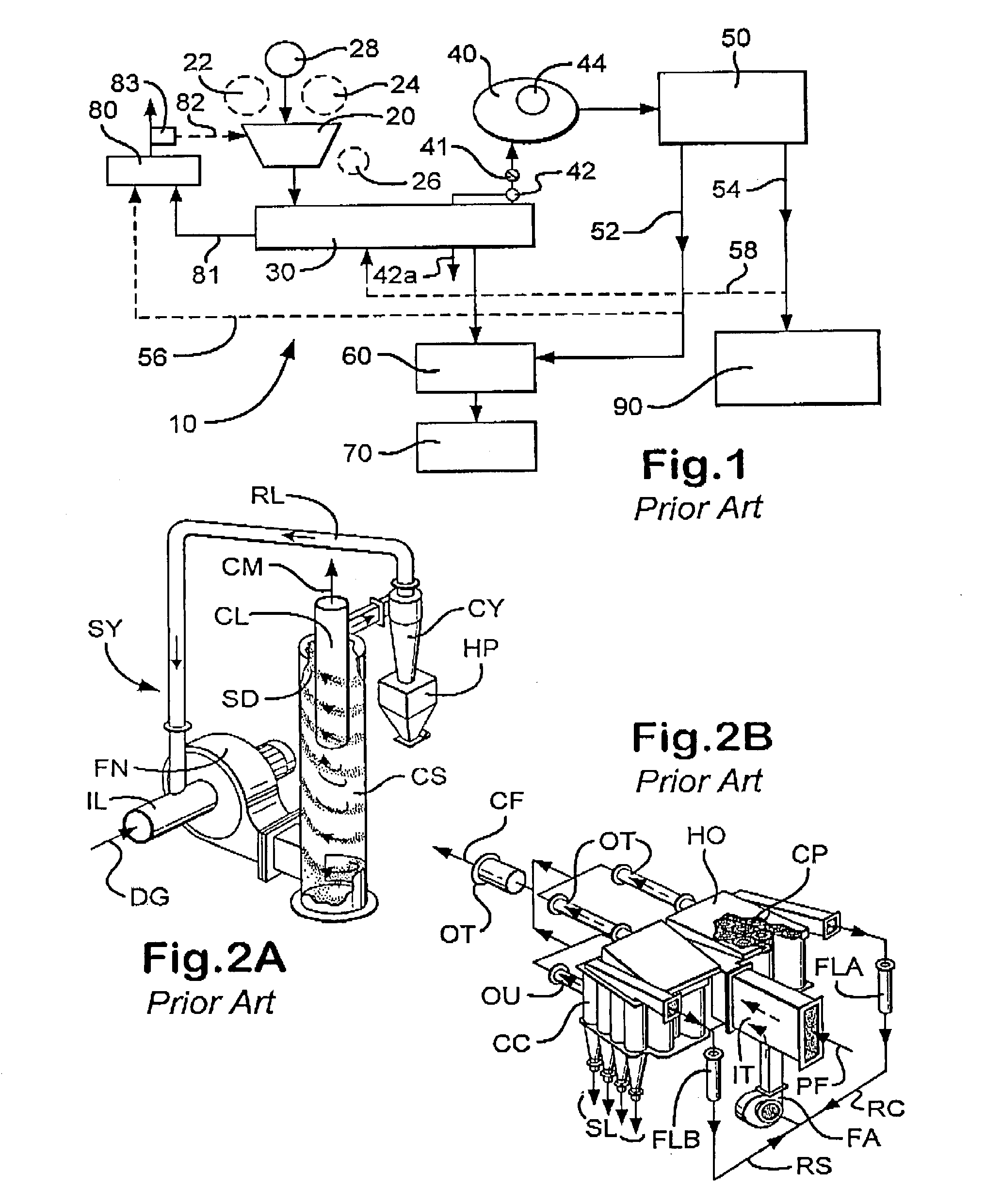
[0058]As shown in FIG. 1, one particular embodiment of a system 10 according to the present invention has a feed hopper 20; a dryer 30; a condenser 40; an oil / water separator 50; a rehydration system 60; a discharge 70; an exhaust stack 80; and an oil processor 90. But for additions and changes according to the present invention as described in detail below, FIGS. 1, 5, 5 and 9 describe prior art.

[0059]Initially, cuttings in a drilling fluid are processed by a rig's shaker system, producing fluid, soil, and oily contaminated cuttings and solids (collectively “oily solids”). These oily solids in a slurry of solids, oil and water are fed to the feed hopper 20 (e.g. from: an end loader; conveyor belt; auger; vacuum system from the shakers; mud cleaner, hydrocyclone and / or centrifuge).

[0060]The feed hopper may include appropriate crushers, shredders, and / or classifiers. A “grizzly unit” (i.e. a screening system with relatively large openings) may be used positioned over the top of the f...


PUM

PropertyMeasurementUnit
diameteraaaaaaaaaa
temperaturesaaaaaaaaaa

Abstract

A method for treating material, the material contaminated with contaminants, the method including: introducing material with contaminants to a system for remediation including a thermal treatment system, a quench system, a weir tank system and a condensing system; feeding a slurry of the material to the thermal treatment system and heating the material therein producing heated discharge solids and a discharge stream with liquid and solids therein; optionally, discharging the heated discharge solids and feeding them to a mill system; feeding the discharge stream to a quench system producing a cooled discharge stream which is fed to the weir tank system; the weir tank system having a clean side and a dirty side; the cooled discharge stream fed to the dirty side of the weir tank system, and from the weir tank system producing at least one stream of cleaned liquid and a stream with contaminants therein; and, in one particular aspect, remediating drilled cuttings material using such a method.

Description

RELATED APPLICATION[0001]This is a continuation-in-part of U.S. application Ser. No. 10 / 051,314 filed Jan. 18, 2002 now abandoned.BACKGROUND OF THE INVENTION[0002]1. Field of the Invention[0003]The present invention is directed to systems and methods for cleaning contaminated soil and, in one particular aspect, to cleaning wellbore drilling cuttings, either on-shore or offshore.[0004]2. Description of Related Art[0005]In a variety of industrial methods, operations, and processes soil becomes contaminated with contaminants such as hydrocarbons and other volatile organic materials and substances. The prior art discloses a wide range of systems and methods for cleaning such soil and for disposal of such contaminants.[0006]Drilling fluids used in hydrocarbon well drilling, as well known in the prior art, pick up solid cuttings and debris which must be removed if the fluid is to be re-used. Drilling fluid, called “mud,” is typically either water based or oil-based. “Oil” includes, but is...

Claims


Application Information

Patent Timeline
Patent Type & Authority Patents(United States)
IPC IPC(8): E21B21/06B01D17/02B01D21/24C02F1/02
CPCB01D17/0211B01D21/2444B01D21/2461E21B21/066
Inventor STRONG, GARY SPIERCE, DALE A.STONE, LYNDONGADDIS, CLIFFWOOD, BRADFORD RSEYFFERT, KENNETH W.LEE, CECIL
Owner VARCO I P INC
Why Eureka
Try Eureka