System and method for regulating an amount of thermal energy generated by an electrosurgical tool

a technology of thermal energy and thermal energy, applied in the field of power-actuated surgical tools, can solve the problems of limiting the current available tools, vaporizing and forming bubbles, and forming bubbles on the surface of active electrodes, and achieve the effect of facilitating the flow of conductive fluid

Inactive Publication Date: 2007-12-11
STRYKER CORP
View PDF21 Cites 57 Cited by
  • Summary
  • Abstract
  • Description
  • Claims
  • Application Information

AI Technical Summary

Benefits of technology

[0018]This invention is related generally to a new and useful electrosurgical tool. The tool of this invention has a tip assembly with an electrode that facilitates the flow of conductive fluid to constantly rewet the active electrode during low powered operation as well as the eduction of large bubbles / gas pockets away from electrode during higher powered operation. More specifically, the tip assembly is designed to foster convective fluid circulation around the surfaces of the electrode that constantly rewets those surfaces and transports the larger bubbles away from the electrode. This circulation also serves to clean debris away from the electrode. In order to foster this fluid flow, the electrode and a complementary insulator of the tip assembly of this invention are formed with portals through which this fluid flows.

Problems solved by technology

However, there are still some limitations associated with the currently available tools.
Some of these limitations are due to the fact that, when an electrosurgical tool is operated in the ablation mode, bubbles form on the surface of the active electrode.
The heating of this solution causes it to vaporize and form bubbles.
However, when additional thermal or electromagnetic energy is radiated from the surface of the active electrode, the adjacent saline solution is subjected to rapid nucleate boiling.
Moreover, during some high powered cutting modes of operation, the electrical current applied to the solution and surrounding tissue causes electrochemical processes to occur in this tissue and liquid.
The presence of these bubbles interferes with the surgeon's view of the surgical site.
This is especially a problem when the electrosurgical tool is employed in an endoscopic surgical procedure.
However, when a conventional electrosurgical tool is employed in an endoscopic surgical procedure, the bubbles generated in the relatively small confines of the space of the surgical site can significantly block the surgeon's view of the site.
Providing a seal around the handle switches can significantly add to the overall cost and assembly of the tool.
Also, sometimes, even with the best seals, there may be liquid leakage into the handle of an electrosurgical tool.
This leakage, if not promptly detected, at a minimum, can lead to the degradation of the tool performance.
In a worse case scenario, this leakage can cause a conductive path to develop along the outer surface of the handle.
If this occurs, the personnel handling the tool may be subjected to electrical shock.
More particularly thermal capsulary shrinkage of tissue is best performed by heating the tissue to a temperature between 60 and 70° C. If the tissue is heated to a temperature above this range, it may suffer damage.
One disadvantage of the presently available electrosurgical tools is that the transducer internal to the tool only measures the temperature of the adjacent active electrode.
Given the presence of fluids and other material around the active electrode and, more particularly, between the transducer and the surgical site, this measurement may not accurately represent the temperature at the site to which the electrode is applied.
Still another disadvantage associated with the currently available electrosurgical tool relates to the fact that often an AC signal is used to energize the active electrode.
These electromagnetic waves interfere with the generation of the output signal generated by the transducer.
During time periods when the energization signal is pulsed on, the transducer signal is not employed as a feedback signal since it is adversely affected by the stray electromagnetic waves.
One disadvantage of this mechanism is that the pulsing of current through the active electrode may stress the material from which the electrode is formed.
Another disadvantage of this process is that the pulsing causes the thermal energy generated by the electrode to itself be generated in an on / off / on / off pattern.
The cyclic generation of this heat can cause it to be unevenly applied to the surgical site.
The uneven application of this heat can in turn both make it difficult to control the application of heat and lengthen the time it takes to perform the desired thermal capsulary shrinkage procedure.

Method used


Image

  • System and method for regulating an amount of thermal energy generated by an electrosurgical tool
  • System and method for regulating an amount of thermal energy generated by an electrosurgical tool
  • System and method for regulating an amount of thermal energy generated by an electrosurgical tool

Examples


Embodiment Construction

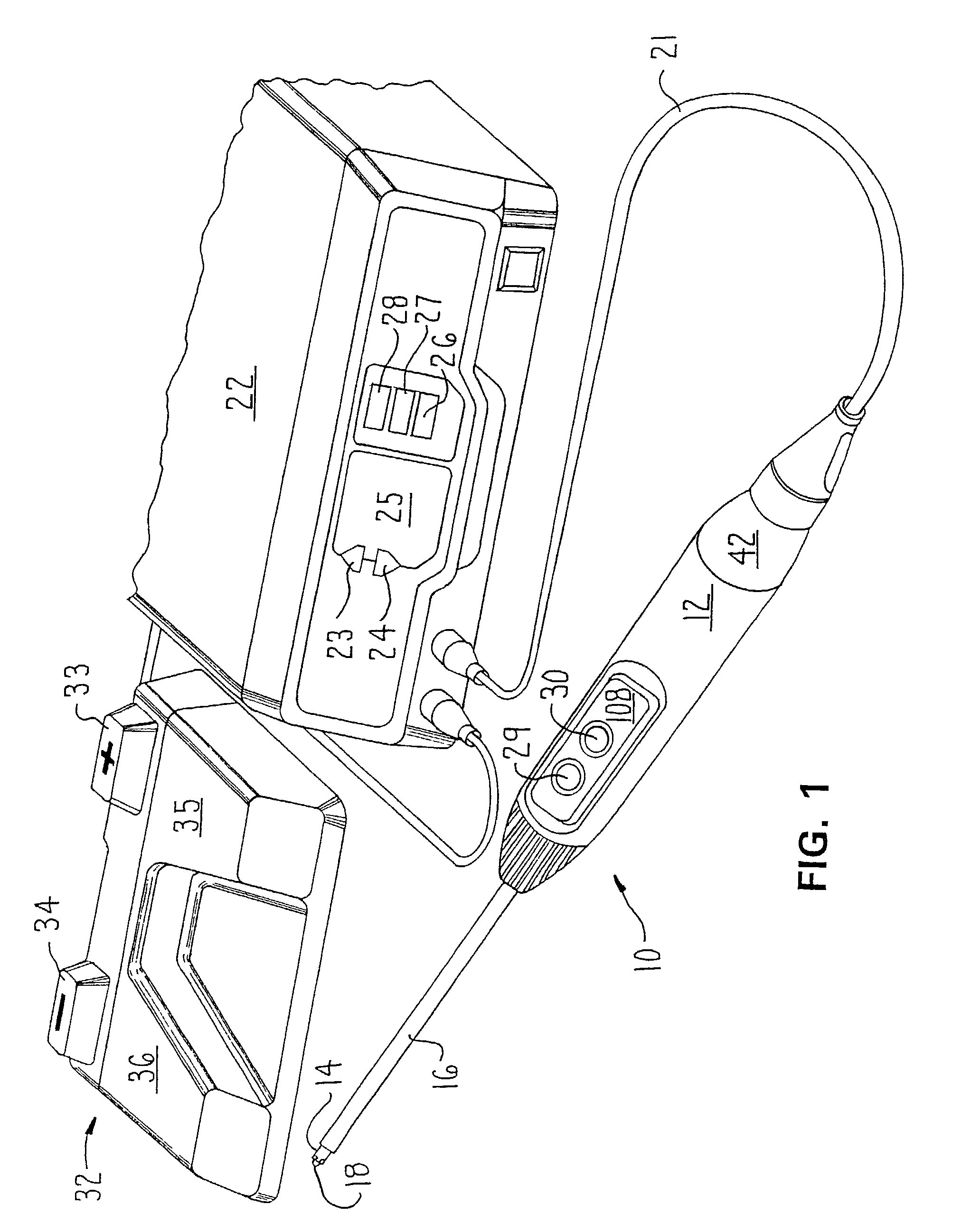
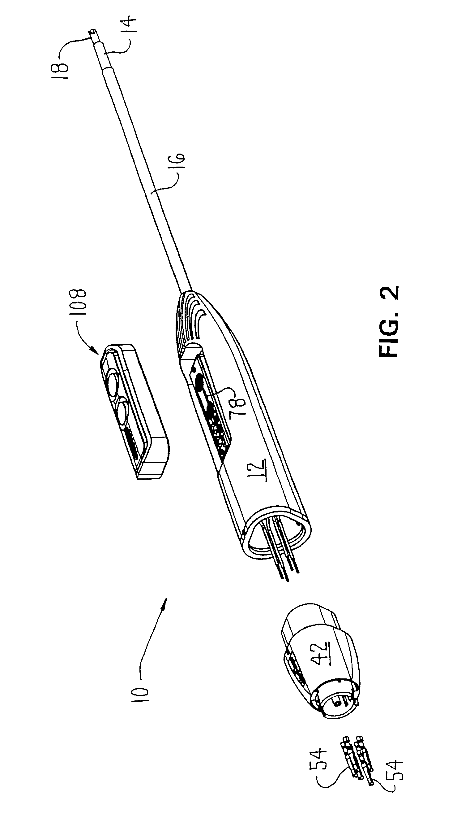
[0057]FIGS. 1 and 2 depict the basic electrosurgical tool 10 of this invention. The tool 10 includes an elongated shell-like nose cone 12 that serves as the handle for the tool. Extending forward from the front end of the nose cone 12 is a shaft 14 formed from conductive metal. (In this application, “front”, “forward” and “distal” shall be understood to mean towards the surgical site to which the tool is applied. “Rear”, “rearwardly” and “proximal” shall be understood to mean away from the surgical site.) Substantially all of the shaft 14, except for its distal end, is covered by an insulating tube 16.

[0058]A tip assembly 18 extends forward from the distal end of shaft 14. An electrode 20 is housed in the tip assembly 18. More precisely, electrode 20 is considered an active electrode and the exposed distal end of shaft 14 functions as a return or reference electrode. When the electrosurgical tool 10 is actuated, current flows from electrode 20 to the exposed end of shaft 14. The cur...


PUM


Abstract

An bipolar electrosurgical tool (10) for cauterizing or ablating tissue. The tool has a nose cone (12) which serves as a handle. A conductive shaft (14) extends from the nose cone. A tip assembly (18) with an active electrode (20) is mounted to the shaft. A circuit board (78) is mounted in the nose cone. Conductive traces that forming contact pads (96, 102) are formed on the circuit board. A web (108) formed from a single piece of elastomeric material is seated over the opening in which the printed circuit board is mounted to seal the opening shut. Integrally formed with the web are buttons (116, 118) that are in registration over the contact pads. The buttons can be depressed downwardly towards the contact pads. When a button is so depressed, a conductive landing pad (120) integral with the button closes the connection between the traces that form the contact pad. Thus, the tool of this invention is provided with switches. The circuit board also has two conductive traces (92, 104a) that run in parallel. If there is a leak into the nose cone, a connection is established across these traces and shorts out a resistor (105). The shorting out of this resistor provides a control console (22) with an indication that there is a leak. The electrode is formed from a single piece of tantalum. The electrode has a head formed with a hole (172) trough which fluid flows. The electrode is seated in a sleeve (136b) provided with a through bore (177) in registration with the electrode hole.

Description

RELATIONSHIP TO EARLIER FILED APPLICATION[0001]This Application is a division of U.S. patent application Ser. No. 09 / 799,817, filed Mar. 5, 2001, now U.S. Pat. No. 6,461,352, which is a continuation-in-part of U.S. patent application Ser. No. 09 / 310,067, filed May 11, 1999, now U.S. Pat. No. 6,214,003. The foregoing applications are incorporated herein by reference.FIELD OF THE INVENTION[0002]This invention is related generally to a power-actuated surgical tool with a handle-mounted self-sealing switch assembly. One particular version of this tool is an electrosurgical tool that has handle-mounted switches, is relatively easy to manufacture, provides an indication if fluid penetrates its handle and that has tip that fosters fluid circulation adjacent the surgical site to which it is applied.[0003]This invention is also related generally to a system and method of shrinking capsulary tissue and, more particularly, to a system and method for shrinking capsulary tissue by applying heat,...

Claims


Application Information

Patent Timeline
Patent Type & Authority Patents(United States)
IPC IPC(8): A61B18/14
CPCA61B18/148A61B18/1402H01H2300/014A61B2218/002A61B2218/007A61B2017/00482
Inventor MORGAN, ROYSARAVIA, HEBERVOGES, JENSPRAKASH, MANI
Owner STRYKER CORP
Why Eureka
Try Eureka