Electronic oscillators having a plurality of phased outputs and such oscillators with phase-setting and phase-reversal capability

a technology of electronic oscillators and phase outputs, applied in the field of electronic oscillators, can solve problems such as undesirable power dissipation and noise, and achieve the effect of reducing the power consumption of multiphase electronic oscillators

Inactive Publication Date: 2007-12-11
FUJITSU LTD
View PDF24 Cites 23 Cited by
  • Summary
  • Abstract
  • Description
  • Claims
  • Application Information

AI Technical Summary

Benefits of technology

[0008]Accordingly, it is an object of the present inventions to improve the noise characteristics of multiphased electronic oscillators.
[0009]It is another object of the present inventions to decrease the power consumption of multiphased electronic oscillators.

Problems solved by technology

As part of making their inventions, the inventors have recognized that the feedback configurations and termination resistances used in conventional oscillators cause several problems, including noise effects and undesirable power dissipation.

Method used


Image

  • Electronic oscillators having a plurality of phased outputs and such oscillators with phase-setting and phase-reversal capability
  • Electronic oscillators having a plurality of phased outputs and such oscillators with phase-setting and phase-reversal capability
  • Electronic oscillators having a plurality of phased outputs and such oscillators with phase-setting and phase-reversal capability

Examples


third embodiment

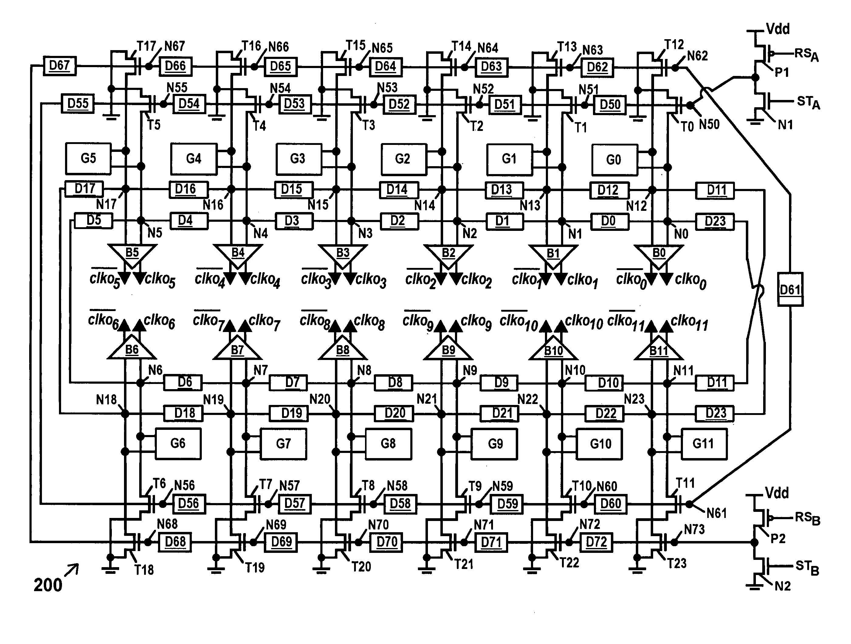
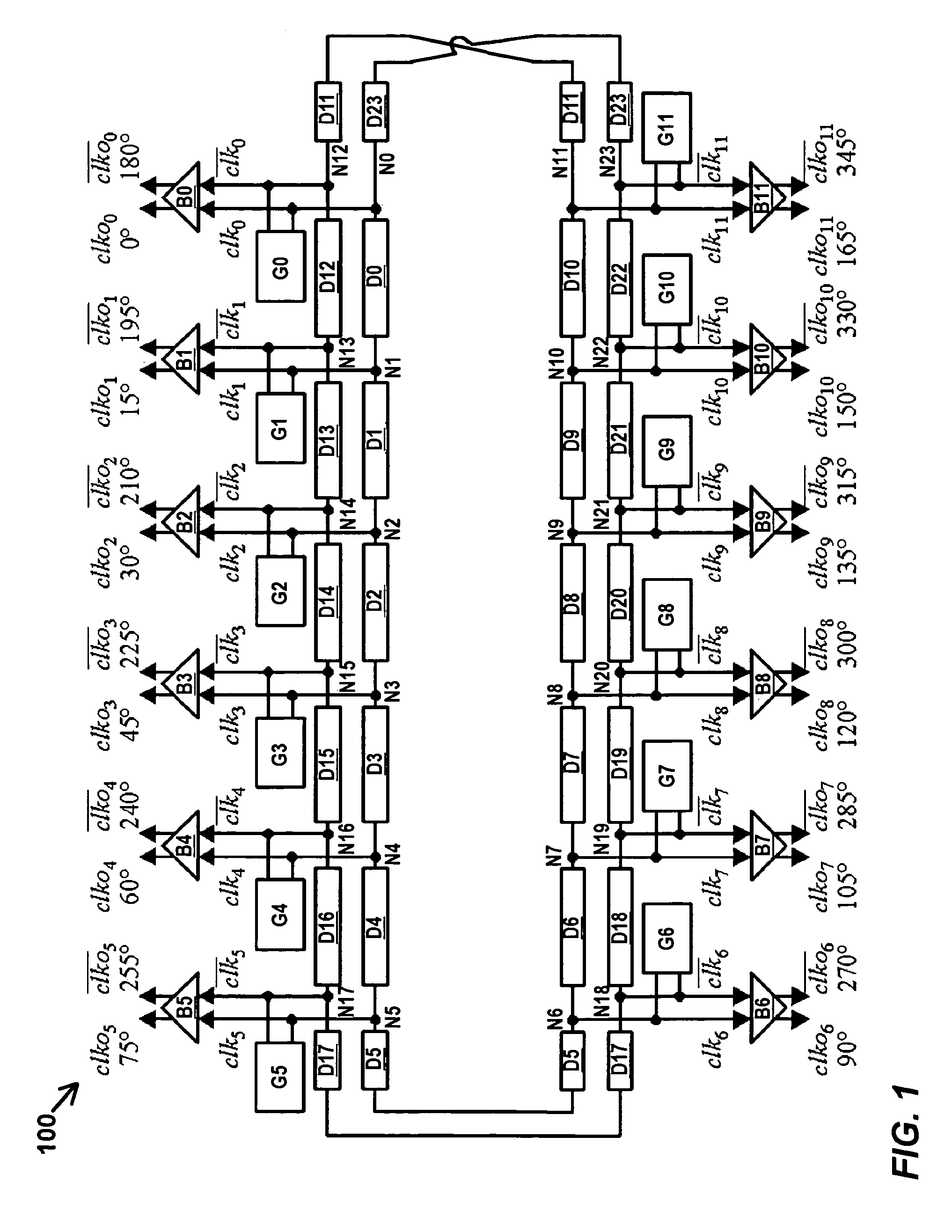
[0044]FIG. 11 shows an oscillator according to the present invention at 300. Oscillator 300 comprises the same components as oscillator 200, except for the omission of delay stages D61-D72 and nodes N62-N73. The components of oscillator 300 are configured the same way as the corresponding components of oscillator 200 except that the output of the circuit formed by transistors N2 and P2 is coupled to node N61 instead of node N73, and except that the modulation terminals of control transistors T12-T23 are coupled to nodes N50-N61, respectively, instead of nodes N62-N73, respectively. As such, the control chain of delay stages only forms one ring around the delay loop, and the same control signal at a control node (N50-N61) controls both pairs of control transistors associated with each negative-resistance element G0-G11. After being placed in the reset state, oscillator 300 is set to one of the two oscillation directions by activating either of signals STA or STB, as described above w...

fourth embodiment

[0045]FIG. 12 shows an oscillator according to the present invention at 400. Oscillator 400 comprises the same components as oscillator 300, except for control transistors T12-T23, which are not used. The components of oscillator 400 are configured the same way as the corresponding components of oscillator 300 except that the first and second conduction terminals of each control transistor T0-T11 are coupled to the first and second outputs, respectively, of a respective negative-resistance element G0-G11, as shown in the figure. Oscillator 400 is reset and thereafter set to oscillate in one of two oscillation directions by the same sequence of steps described above for oscillators 200 and 300. Under reset conditions, each of transistors T0-T11 is conductive, and couples the adjacent nodes of the loop (e.g., adjacent nodes N0 and N12, and so on) together, and sets (clamps) their voltages to substantially the same value. In addition, this presents a positive resistance to both outputs...


PUM


Abstract

Disclosed are multiphase oscillators comprising a plurality of delay stages serially coupled in a loop by a plurality of nodes, with the loop being folded to provide two concentric rings of delay stages with equal numbers of allocated nodes. A second plurality of negative-resistance elements are provided, each element having a first output coupled to a node on the first concentric ring and a second output coupled to a node on the second concentric ring. Each such output switches between first and second voltage levels, and provides a negative resistance to a signal coupled to it during at least a portion of the transition between voltage levels. The outputs of an element switch to opposite voltage levels. With this construction, a high-voltage pulse propagates around the loop of delay stages, with a low-voltage pulse propagating behind it. Also disclosed are circuits to control the direction of pulse propagation.

Description

FIELD OF THE INVENTION[0001]The present invention relates to electronic oscillators, and more particularly to electronic oscillators having a plurality of phased outputs in which the phase direction can be reversed during operation.BACKGROUND OF THE INVENTION[0002]An electronic oscillator provides an output signal which varies between two states in a periodic manner (e.g., an oscillation). The two states typically comprise two voltage levels, but may comprise two current levels. Some electric oscillators are constructed to provide two or more outputs. Each output varies between the two states in the same periodic manner, but there is usually a phase difference in their variations. For example, one output may be 90-degrees farther ahead in the periodic variation than another output. Such oscillators are often called multiphased oscillators, polyphase oscillators, or oscillators with multiple-phase outputs.[0003]Many electronic oscillators also include circuitry that allows the freque...

Claims


Application Information

Patent Timeline
Patent Type & Authority Patents(United States)
IPC IPC(8): H03B27/00
CPCH03K3/0315H03B27/00
Inventor TZARTZANIS, NESTORWALKER, WILLIAM W.
Owner FUJITSU LTD
Why Eureka
Try Eureka