Transparent multi-mode PAM interface

a multi-mode, transparent technology, applied in the direction of duplex signal operation, pulse technique, baseband system details, etc., can solve the problems of low latency of parallel buses, inflicting costs on system design, and blocking performance originating in data links

Active Publication Date: 2007-12-11
RAMBUS INC
View PDF5 Cites 102 Cited by
  • Summary
  • Abstract
  • Description
  • Claims
  • Application Information

AI Technical Summary

Problems solved by technology

Use of low-speed and high-latency data links in modern systems often results in bottlenecks to performance originating in the data links.
Backplane environments are especially difficult to signal over.
However, the low latency of parallel buses inflicts costs on a system design.
This trace-matching wastes valuable real estate on a printed circuit board, may require extra board layers, and considerably complicates system-level design.
A key factor that impacts the costs of both parallel and serial data links is manufacturability.
Traditionally, serial link transceivers have been regarded as difficult to implement, requiring mixed signal expertise, tuned integrated circuit (IC) processes and special care during the silicon design flow.
This complexity, however, is not compatible with the large installed base of application logic.

Method used


Image

  • Transparent multi-mode PAM interface
  • Transparent multi-mode PAM interface
  • Transparent multi-mode PAM interface

Examples


Embodiment Construction

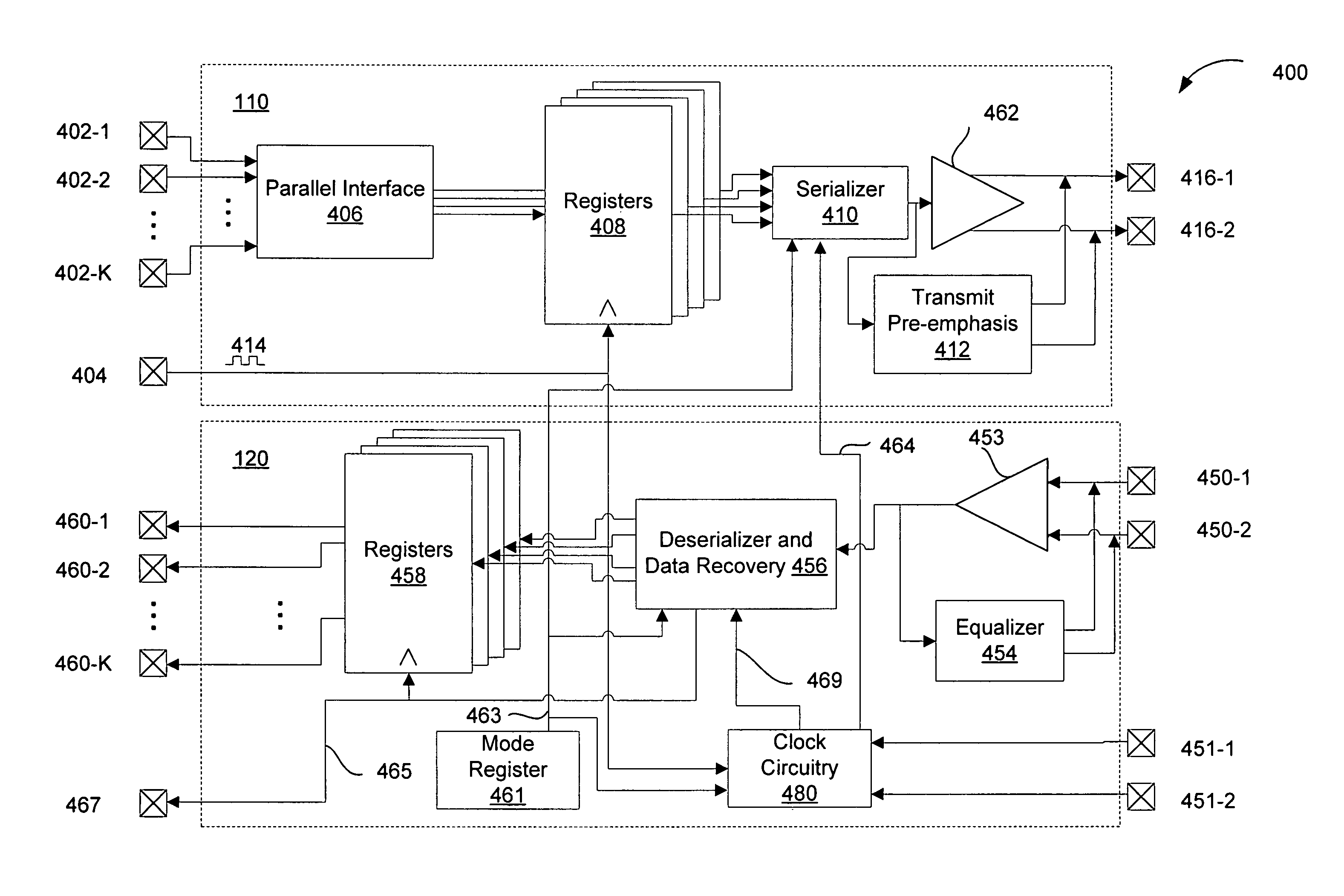
[0049]One aspect of the present invention provides a multi-mode PAM output driver for driving a sequence of symbols. The output driver includes an input interface configured to receive data to be output as the sequence of symbols. Additionally, a PAM mode signal specifies a PAM mode. The output driver further includes multiplexer circuitry configured to output the received data in an order determined by the PAM mode signal. Additionally, a clock circuit is configured to generate an output clock having a clock rate determined by the PAM mode signal. The output driver also includes a driver circuit coupled to the clock circuit and to an output of the multiplexer circuit. The driver circuit is configured to drive the received data as ordered by the multiplexer circuit so as to output the sequence of symbols. Some embodiments of the multi-PAM mode output driver further include control circuitry configured to determine the PAM mode.

[0050]In some embodiments, the sequence of symbols are N...


PUM


Abstract

Provided are a method and apparatus for high-speed, multi-mode PAM symbol transmission. A multi-mode PAM output driver drives one or more symbols, the number of levels used in the PAM modulation of the one or more symbols depending on the state of a PAM mode signal. Additionally, the one or more symbols are driven at a symbol rate, the symbol rate selected in accordance with the PAM mode signal so that a data rate of the driven symbols is constant with respect to changes in the state of the PAM mode signal. Further provided are methods for determining the optimal number of PAM levels for symbol transmission and reception in a given physical environment.

Description

[0001]This application claims priority on U.S. provisional patent application 60 / 515,179, filed Oct. 27, 2003, which is hereby incorporated by reference.FIELD OF THE INVENTION[0002]The present invention relates to the field of systems for data transmission and reception, and in particular the present invention relates to a system and method of providing an interface to a high-speed, multi-PAM mode serial data link.BACKGROUND OF THE INVENTION[0003]The continually increasing demand for high-speed data transmission, together with the continually increasing speeds of central processors, requires the development of low-latency, high-speed data links. Use of low-speed and high-latency data links in modern systems often results in bottlenecks to performance originating in the data links.[0004]Not only are high-speeds and low-latencies required for modern data transmission, performance in a wide variety of physical conditions is also critical. For example, starting in 2004, the serial link-...

Claims


Application Information

Patent Timeline
Patent Type & Authority Patents(United States)
IPC IPC(8): H03K9/02H04L1/00H04L5/14H04L25/02H04L25/03H04L25/49H04L27/08
CPCH04L1/0003H04L5/1438H04L25/4917H04L27/08H04L25/028H04L2025/03585H04L25/0292H04L27/32H04L5/14H04L69/32
Inventor ZERBE, JARED L.WERNER, CARL W.STONECYPHER, WILLIAM F.CHEN, FRED F.
Owner RAMBUS INC
Why Eureka
Try Eureka