Optical receiver and method for controlling dispersion compensation

a technology of optical receiver and compensation, applied in the direction of optical elements, multiplex communication, instruments, etc., can solve the problems of chromatic dispersion including high-order dispersion in optional fiber transmission lines, difficult to realize proper dispersion compensation using a fixed amount of dispersion compensation, and the inability to monitor the quality of the signal directly by converting an optical signal into an electric signal

Inactive Publication Date: 2007-12-11
NAT INST OF INFORMATION & COMM TECH
View PDF24 Cites 10 Cited by
  • Summary
  • Abstract
  • Description
  • Claims
  • Application Information

AI Technical Summary

Benefits of technology

[0027]Preferably, the first dispersion compensator comprises a dispersion / dispersion slope compensator having variable amount of dispersion compensation and variable dispersion slope. The dispersion slope of the dispersion / dispersion slope compensator is controlled so that the transmission error rate of the optical transmission line obtained from the output signal light from the first dispersion compensator becomes smaller.
[0028]Furthermore, in one embodiment, a second dispersion compensator is disposed separately from a first dispersion compensator on the main track to determine an appropriate amount of dispersion compensation. The autocorrelation of a signal light output from the second dispersion compensator is operated and the second dispersion compensator is controlled on trial so that the autocorrelation becomes larger. The first dispersion compensator is initialized according to the trial result. Then, an autocorrelation of a signal light output from the first dispersion compensator is operated and the first dispersion compensator is controlled so that the autocorrelation becomes larger and a transmission error rate of the optical transmission line obtained from the signal light output from the first dispersion compensator becomes smaller.
[0029]Preferably, the first dispersion compensator comprises a dispersion / dispersion slope compensator having variable amount of dispersion compensation and variable dispersion slope. The dispersion slope of the dispersion / dispersion slope compensator is controlled so that a transmission error rate of the optical transmission line obtained from the signal light output from the first dispersion compensator becomes smaller.

Problems solved by technology

Accordingly, in ultra high speed optical pulse transmission systems in which a bit rate per wavelength becomes 160 Gb / s or more, the influence by chromatic dispersion including high-order dispersion in optional fiber transmission line becomes serious.
In ultra high-speed optical pulse transmission systems in which a bit rate per wavelength is 160 Gb / s or more, it is difficult to realize proper dispersion compensation using a dispersion compensating device of a fixed amount of dispersion compensation.
If its bit rate is 160 Gb / s or more, it is impossible to monitor a signal quality by directly converting an optical signal into an electric signal.
However, generally, a system to monitor quality of a signal of 10 Gb / s or more requires an expensive electronic circuit and the monitored results includes deterioration of signal quality due to the DEMUX.
When the deterioration of signal quality between tributary channels is varied, it sometimes causes wrong operation of dispersion control.

Method used


Image

  • Optical receiver and method for controlling dispersion compensation
  • Optical receiver and method for controlling dispersion compensation
  • Optical receiver and method for controlling dispersion compensation

Examples


Embodiment Construction

[0039]Explanatory embodiments of the invention are explained below in detail with reference to the drawings.

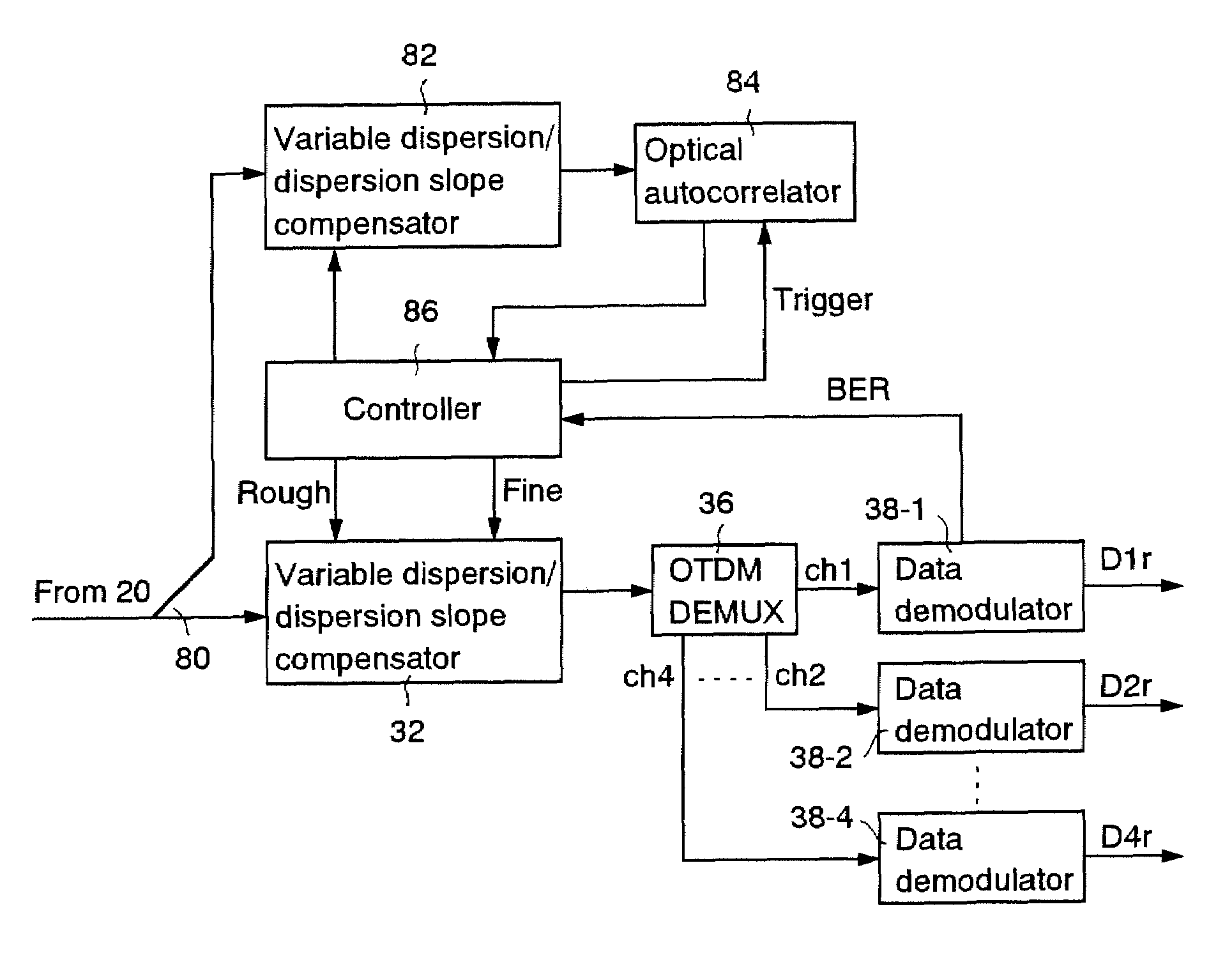
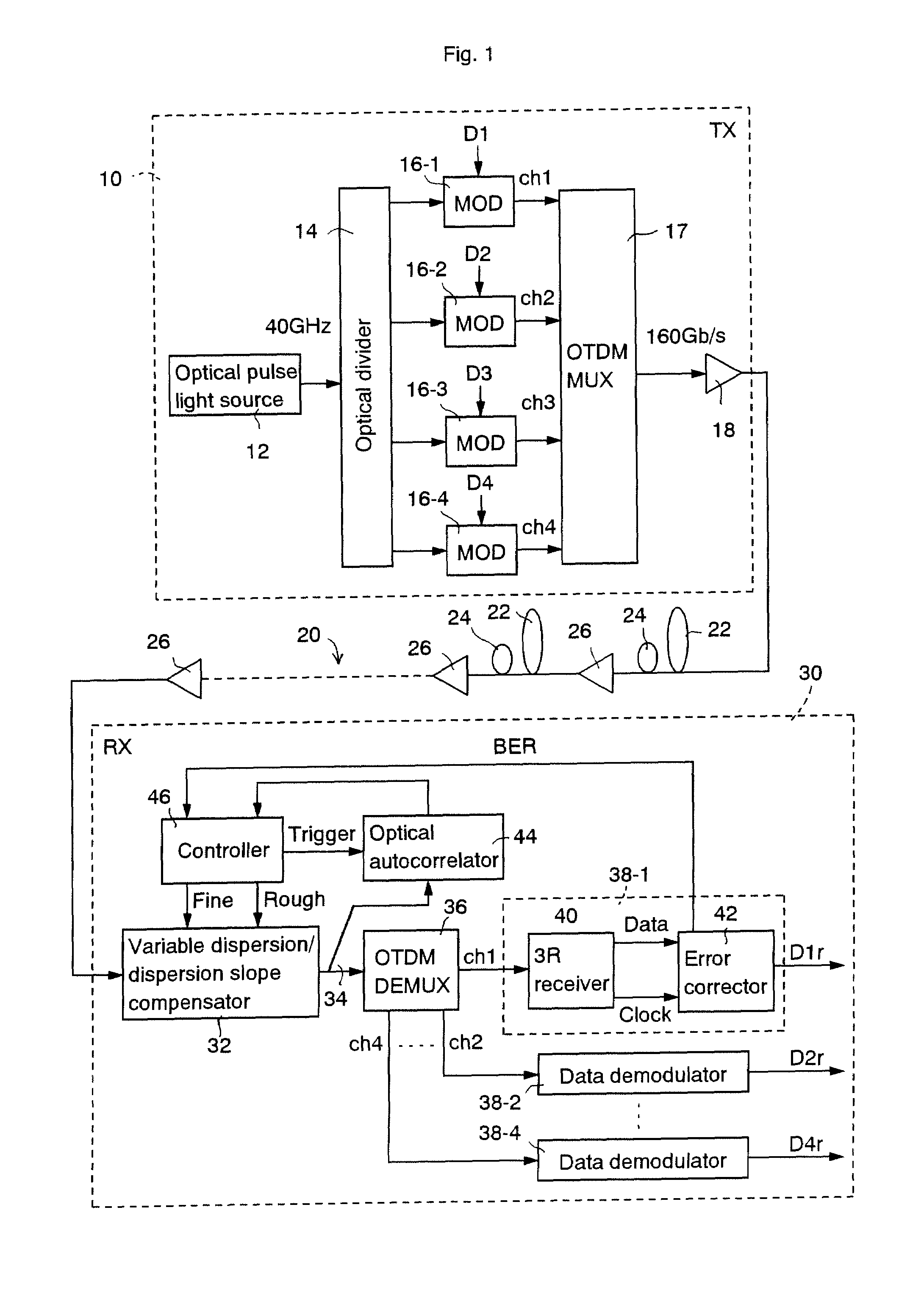
[0040]FIG. 1 shows a schematic block diagram of an explanatory embodiment according to the invention. A system of this explanatory embodiment comprises an optical transmitter 10, a dispersion compensating optical transmission line 20, and an optical receiver 30.

[0041]The configuration and operation of the optical transmitter 10 is explained below. A pulse light source 12 outputs a pulse train of single wavelength λs. Here, it is assumed as an example, that the pulse light source 12 outputs an optical pulse train of 40 GHz. An optical divider 14 divides the output pulse from the pulse light source 12 into four portions and applies them to data modulators 16-1 to 16-4 respectively. The data modulator 16-1 binary-modulates amplitude of the optical pulse train from the optical divider 14 according to a data D1. Similarly, the modulators 16-2 to 16-4 binary-modulate amplitudes of t...


PUM


Abstract

An optical receiver including an optical divider to divide a signal light from an optical transmission line into two portions, a first and a second dispersion compensators, each dispersion compensator having variable dispersion compensation to compensate chromatic dispersions of each of the two portions of signal light output from the optical divider, and a data demodulator to demodulate a data carried by a signal light output from the first dispersion compensator. The optical receiver further includes an optical autocorrelator to operate on a signal light output from the second dispersion compensator and a controller to control the second dispersion compensator to increase autocorrelation of the optical autocorrelator, and to control the first dispersion compensator according to the result of said controlling the second dispersion compensator.

Description

CROSS REFERENCE TO RELATED APPLICATIONS[0001]This application claims priority to Japanese Patent Application No. 2003-070418, filed Mar. 14, 2003, the entire contents of which are incorporated herein by reference.FIELD OF THE INVENTION[0002]This invention relates to an optical receiver and method for controlling dispersion compensation.BACKGROUND OF THE INVENTION[0003]In a long haul high speed optical transmission system, especially in an optical transmission line for transmitting a signal light of multiple wavelengths through wavelength division multiplexing, it is required to compensate chromatic dispersion and, if necessary, dispersion slope. For instance, optical transmission systems for compensating dispersion and dispersion slope and compensators thereof are described in the following issued patents:[0004]U.S. Pat. No. 6,496,615,[0005]U.S. Pat. No. 6,490,398,[0006]U.S. Pat. No. 6,453,093,[0007]U.S. Pat. No. 6,445,864,[0008]U.S. Pat. No. 6,430,347,[0009]U.S. Pat. No. 6,363,184,...

Claims


Application Information

Patent Timeline
Patent Type & Authority Patents(United States)
IPC IPC(8): H04B10/06H04B10/14H04B10/18H04B10/2507G02B6/28H04B10/07H04B10/2519H04B10/2525H04J14/00H04J14/02
CPCH04B10/25133G02B6/2861
Inventor MIYAZAKI, TETSUYA
Owner NAT INST OF INFORMATION & COMM TECH
Why Eureka
Try Eureka