High pressure gaseous fuel supply system for an internal combustion engine and a method of sealing connections between components to prevent leakage of a high pressure gaseous fuel

a gaseous fuel and internal combustion engine technology, applied in the direction of fuel supply equipment, fuel systems, fuel injection equipment, etc., can solve the problems of cost, availability and emissions benefits, present day gaseous-fuelled engines cannot match the performance and efficiency of diesel-fuelled engines, and no one has addressed the problem of sealing connections between components, so as to reduce the level of regulated emissions

Inactive Publication Date: 2007-12-18
WESTPORT POWER
View PDF22 Cites 64 Cited by
  • Summary
  • Abstract
  • Description
  • Claims
  • Application Information

AI Technical Summary

Benefits of technology

[0019]To provide a fluid tight seal, the resilient member is preferably held in compression when installed at the interface. The resilient member can be in the simple shape of a closed circular ring, which is advantageous for strength and ease of manufacturing. In cross-section, the resilient member can be round. However, those skilled in the technology will understand that other cross-section shapes can also be used with similar results. For example, for a face-seal application the resilient member could also be in the form of a gasket or a ring seal can be employed with a cross or “X” shaped cross-section.
[0021]In preferred embodiments, the gaseous fuel can be a combustible hydrocarbon derivative. For example, the gaseous fuel can be selected from the group consisting of natural gas, methane, propane, ethane. The gaseous fuel could also be hydrogen or a blend of any of the aforementioned gaseous fuels. For example, a blend of 20% hydrogen and 80% natural gas has been tested as a fuel in internal combustion engines as a means for reducing the level of regulated emissions from the engine's exhaust system.
[0022]The fuel conditioning module comprises a pressure regulating device to control the pressure of the gaseous fuel within the fuel injection valve. In a preferred embodiment, the pressure regulating device is operable to control fluid pressure within the fuel injection valve to fluctuate within a range of pressures between about 17 MPa and up to about 70 MPa during normal operation of the components and more preferably gas pressure is controllable to be between at least 19 MPa and 35 MPa. The pressure regulating device can be a dome-loaded regulator with a piston moveable under the influence of a control fluid. The resilient member can provide a dynamic seal between the piston and the cylinder within which it is disposed.

Problems solved by technology

Using such gaseous fuels instead of liquid diesel fuel generally results in cost, availability and emissions benefits.
However, a challenge of this approach is that the gaseous fuel must be delivered to the combustion chamber at a pressure that overcomes the high in-cylinder pressures that are present during this part of the engine cycle.
However, present day gaseous-fuelled engines have been unable to match the performance and efficiency of diesel-fuelled engines.
With present day gaseous fuelled engines there is no need to supply gaseous fuel at pressures above 17 MPa (about 2500 psi) and no one has addressed the problem of sealing connections between components to prevent the leakage of a gaseous fuel supplied at such pressures, especially for an application where the gas pressure can also quickly fluctuate between very high pressures and much lower pressures.
These seals were found to fail after a short time.
It is believed that the pressure fluctuations between operating pressure and atmospheric pressure was the primary cause of failure.
The problem of explosive decompression can occur when the fluid is a gas, which is at relatively high pressures and when the system is subjected to rapid pressure fluctuations.
Manufacturers of seals do not normally rate a seal material's effectiveness against explosive decompression, making difficult the selection of an appropriate seal material.

Method used


Image

  • High pressure gaseous fuel supply system for an internal combustion engine and a method of sealing connections between components to prevent leakage of a high pressure gaseous fuel
  • High pressure gaseous fuel supply system for an internal combustion engine and a method of sealing connections between components to prevent leakage of a high pressure gaseous fuel
  • High pressure gaseous fuel supply system for an internal combustion engine and a method of sealing connections between components to prevent leakage of a high pressure gaseous fuel

Examples


Embodiment Construction

)

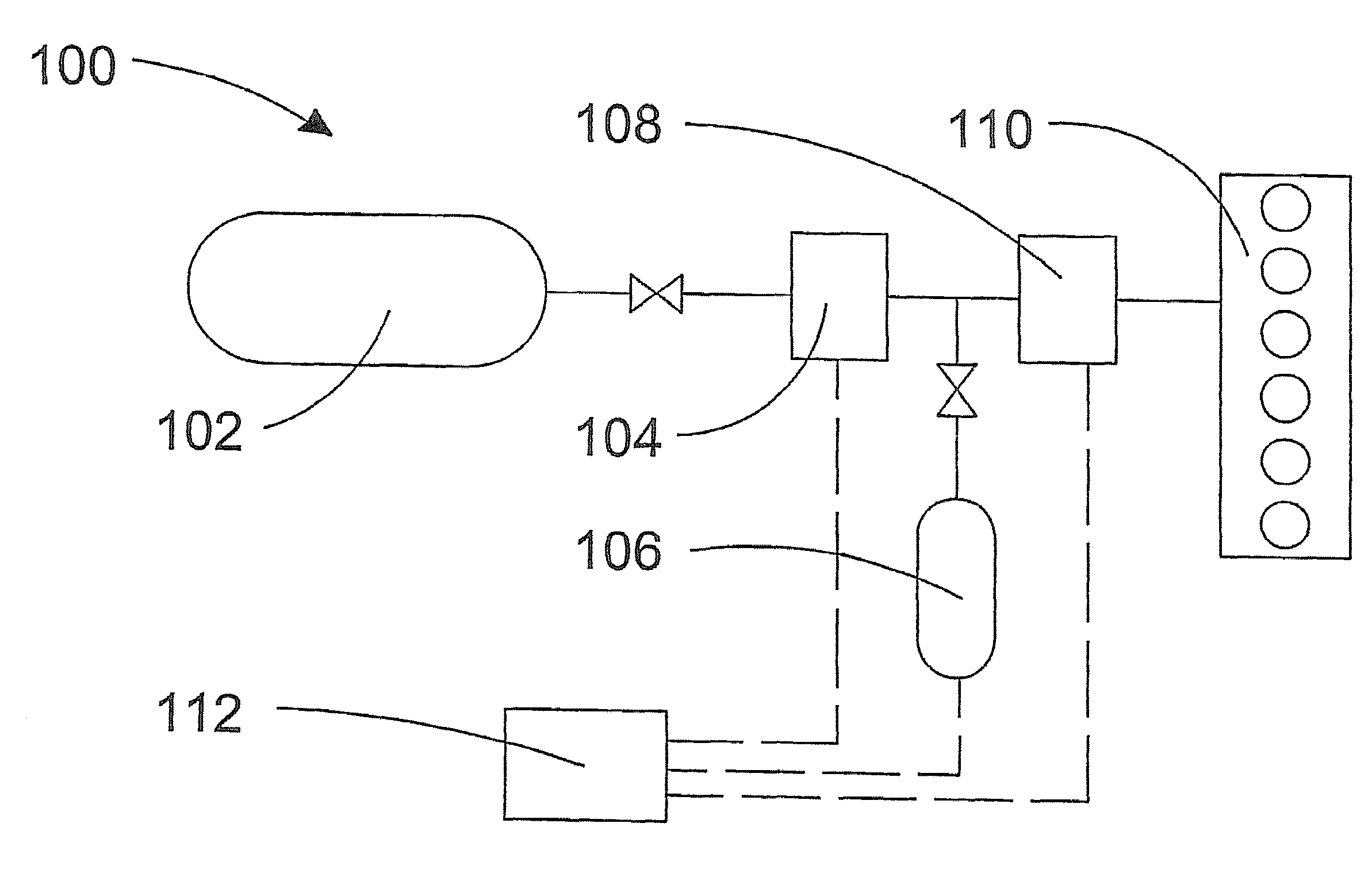
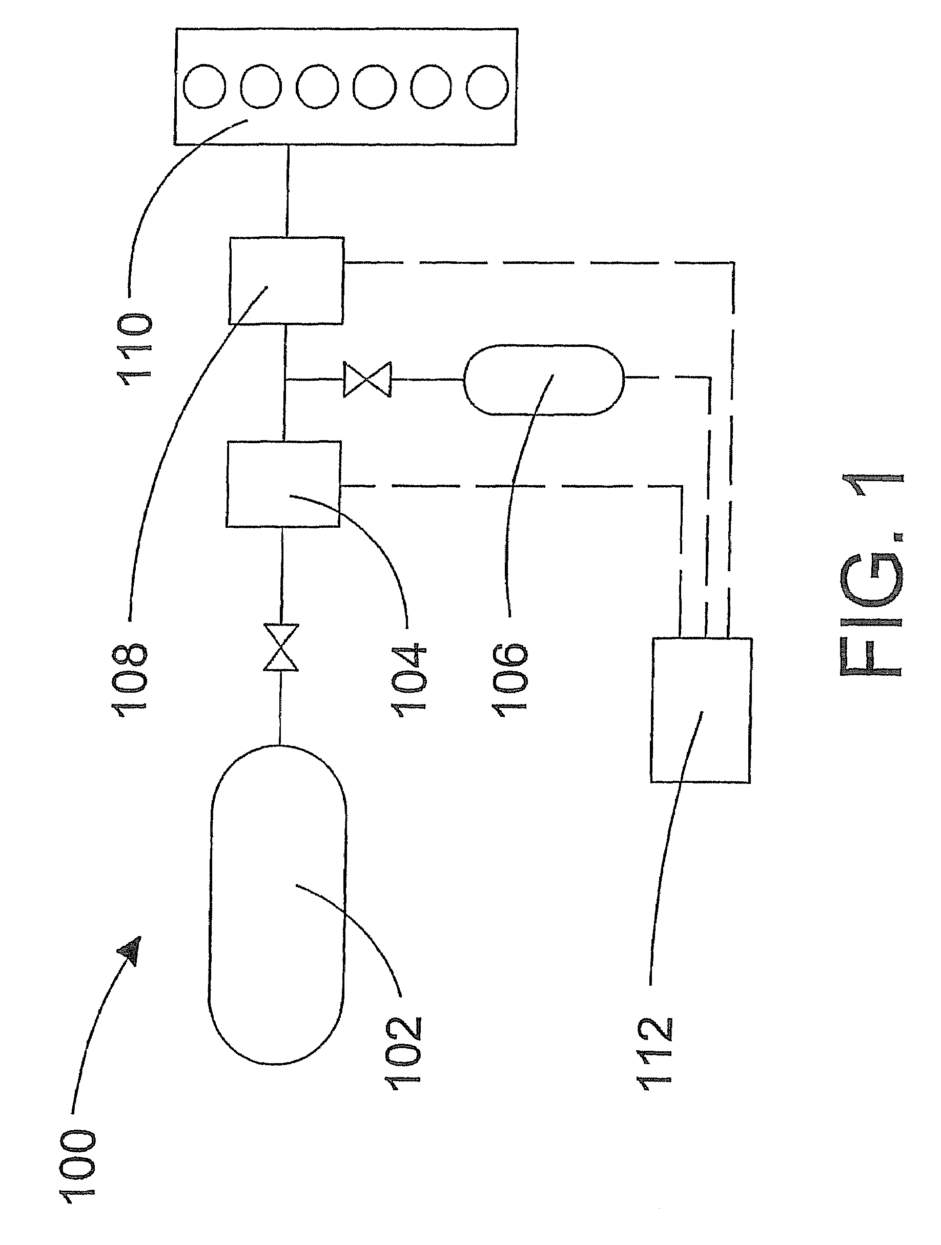
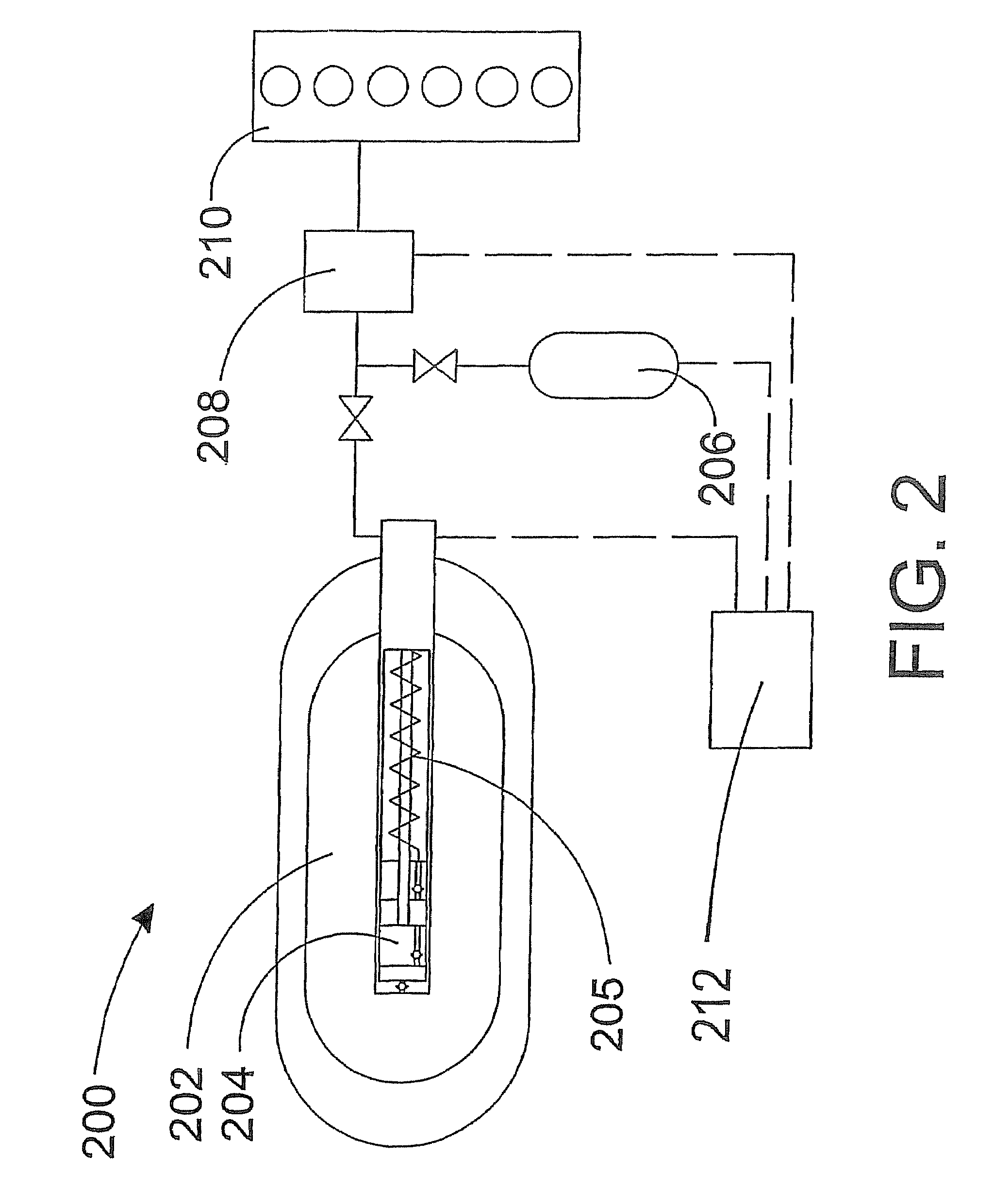
[0040]In order to introduce a gaseous fuel directly into a combustion chamber near the end of the compression stroke, it is necessary to supply the fuel to a fuel injection valve at a pressure that is between at least 17 MPa and about 70 MPa. The fuel injection valve for introducing the gaseous fuel directly into the combustion chamber is typically inserted through the cylinder head, with a nozzle tip projecting into the combustion chamber. During engine operation, the constant temperature of the cylinder head around the fuel injection valve and its associated component seals can approach about 200° C. (about 392° F.), particularly where the fuel injection valve is closest to the combustion chamber and the exhaust manifold ports. Since conventional gaseous-fuelled engines have employed lower pressure fuel systems associated with forming a premixed fuel charge in the intake manifold, the problem of providing suitable seals for handling a gaseous fuel at higher pressures and temperat...


PUM


Abstract

A high-pressure fuel system supplies gaseous fuel to an internal combustion engine. Gaseous fuel pressure within the system is at least 17 MPa during normal operation. The system comprises a number of components and conduits and at least one resilient member for sealing at an interface between two components. The resilient member consists essentially of thermoplastic polyurethane. A corresponding method provides sealing between components containing gaseous fluids at pressures that can be above 17 MPa, in which the gaseous fluids routinely undergo rapid reductions in pressure. The method comprises disposing a resilient member, which consists essentially of thermoplastic polyurethane, at an interface between the components. Gas pressure fluctuations can occur during operation of the components or when the high-pressure gas is vented from the components upon shut down of the high-pressure system. A particularly suitable application for the present method is high-pressure gaseous fuel supply systems for internal combustion engines.

Description

CROSS-REFERENCE TO RELATED APPLICATION(S)[0001]This application is a continuation of International Application No. PCT / CA2004 / 001667, having an international filing date of Sep. 10, 2004, entitled “High Pressure Gaseous Fuel Supply System For An Internal Combustion Engine And A Method Of Sealing Connections Between Components To Prevent Leakage Of A High Pressure Gaseous Fuel”. International Application No. PCT / CA2004 / 001667 claimed priority benefits, in turn, from Canadian Patent Application No. 2,441,641 filed Sep. 23, 2003. International Application No. PCT / CA2004 / 001667 is hereby incorporated by reference herein in its entirety.FIELD OF THE INVENTION[0002]The present invention relates to a high-pressure gaseous fuel supply system for an internal combustion engine and a method of sealing connections at interfaces between components to prevent leakage of a high-pressure gas. More particularly, the subject apparatus and method provides a seal for gaseous fluids in environments wher...

Claims


Application Information

Patent Timeline
Patent Type & Authority Patents(United States)
IPC IPC(8): F02B43/00F02M21/02F02M55/00F02M61/04F02M63/02
CPCF02M55/005F02M61/04F02M63/0225F02M21/0293F02M21/0296F02M21/0239F02M21/0263Y02T10/32F02M21/0221F02M21/0287F02M21/0215Y02T10/30
Inventor POST, ADRIAN J.BROOK, THOMAS C.
Owner WESTPORT POWER
Why Eureka
Try Eureka